
Cooling roller

A technology of cooling roll and annular cooling, which is applied in the field of cooling rolls, can solve the problems of inconvenient operation of the overall equipment, poor cooling effect, uneven cooling, etc., and achieve uniform and efficient cooling and cooling treatment, improved forming effect, and good cooling effect

Inactive Publication Date: 2017-08-18
QINGDAO YUNLU ADVANCED MATERIALS TECH CO LTD
View PDF7 Cites 5 Cited by
  • Summary
  • Abstract
  • Description
  • Claims
  • Application Information

AI Technical Summary

Problems solved by technology

Due to the limitations of the respective structures of the above-mentioned various cooling rolls, there are phenomena such as low cooling efficiency, poor cooling effect, uneven cooling, etc., which cause inconvenience to the overall operation of related equipment

Method used


Image

  • Cooling roller
  • Cooling roller
  • Cooling roller

Examples


Embodiment Construction

[0022] The core of the present invention is to provide a cooling roll whose cooling process is relatively uniform and efficient.

[0023] In order to enable those skilled in the art to better understand the solution of the present invention, the present invention will be further described in detail below in conjunction with the accompanying drawings and specific embodiments.

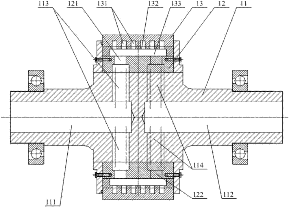
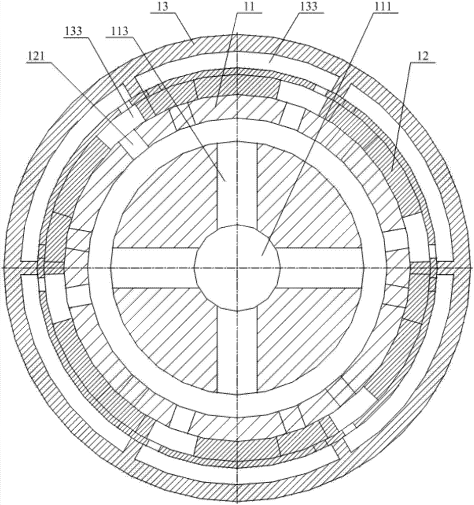
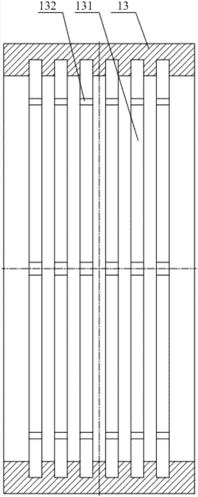
[0024] Please refer to Figure 1 to Figure 3 , figure 1 A sectional view of the front structure of the cooling roll provided for a specific embodiment of the present invention; figure 2 for figure 1 A cross-sectional view of the side structure at the end where the middle water inlet pipe is located; image 3 for figure 1 Sectional view of the structure of the middle copper sleeve.

[0025] In a specific embodiment, the cooling roll provided by the present invention includes a main shaft 11, the outer peripheral portion of the main shaft 11 is covered with a support member 12, the outer peripheral p...


PUM


Abstract

The invention discloses a cooling roller. The cooling roller comprises a main shaft. The periphery of the main shaft is sleeved with a supporting piece. The periphery of the supporting piece is sleeved with a copper sleeve. A water inlet pipe which extends in the axial direction of the main shaft is arranged in the middle of the one end of the main shaft, and a drain pipe which extends in the axial direction of the main shaft is arranged in the middle of the other end of the main shaft. A plurality of annular cooling grooves which extend in the circumferential direction of the copper sleeve and are sequentially distributed in the axial direction of the copper sleeve are formed in the inner wall of the copper sleeve. A first water inlet branch penetrates through the side wall of the water inlet pipe. A first drain branch penetrates through the side wall of the drain pipe. A second water inlet branch and a second drain branch penetrate through the supporting piece. The water inlet pipe, the first water inlet branch, the second water inlet branch and the annular cooling groove sequentially communicate in the water flow direction. The annular cooling grooves, the second drain branch, the first drain branch and the drain pipe sequentially communicate in the water flow direction. The cooling process of the cooling roller is uniform and efficient.

Description

technical field [0001] The invention relates to the technical field of supporting components of amorphous strip production equipment, in particular to a cooling roll. Background technique [0002] In the existing processing and production process of products involving molten state casting such as amorphous strips, cooling rolls are usually used to perform cooling and forming operations on the products. [0003] The current cooling roll usually includes three types of structures: one is that there is no groove structure on the copper sleeve and the support, and the cooling is performed only by passing cooling water through the gap between the components; the other is that only the cooling groove structure is set on the support. Cooling water is passed into the cooling groove of the monomer component to lower the temperature; the third is to only slot axially on the copper sleeve, and the cooling water is passed into the groove to reduce the temperature. Due to the limitation...

Claims


Application Information

Patent Timeline
IPC IPC(8): B22D11/06
CPCB22D11/0682
Inventor 庞靖李晓雨李庆华刘树海
Owner QINGDAO YUNLU ADVANCED MATERIALS TECH CO LTD
Learn More