Anti-reflection method for beam sampling grating in intense laser system

A technology of sampling gratings and strong lasers, applied in the direction of diffraction gratings, optics, optical components, etc., can solve the problems of laser damage threshold decrease in transmittance, film pollution, transmittance and damage threshold decrease, etc., to achieve performance and stability Sexual problems, stable performance

Active Publication Date: 2017-08-11
UNIV OF SCI & TECH OF CHINA
View PDF4 Cites 4 Cited by
  • Summary
  • Abstract
  • Description
  • Claims
  • Application Information

AI Technical Summary

Problems solved by technology

[0004] However, due to its loose and porous structure, the silica sol-gel anti-reflection film will absorb organic matter in the environment and cause its own pollution, resulting in transmittance and damage severe drop in threshold
The adsorbed organic matter will change its own refractive index (equivalent refractive index). If the anti-reflection coating is used on the beam sampling grating surface, it will change the -1 order diffraction efficiency and the overall uniformity, which will lead to inaccurate diagnosis. Therefore

Method used


Image

  • Anti-reflection method for beam sampling grating in intense laser system
  • Anti-reflection method for beam sampling grating in intense laser system
  • Anti-reflection method for beam sampling grating in intense laser system

Examples


Embodiment 1

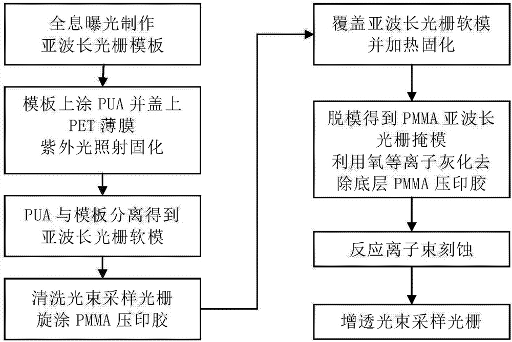
[0036] Embodiment 1: this specific implementation mode is to make size be 100 * 100mm 2 The anti-reflection beam sampling grating. Including the following specific steps, such as figure 1 Shown:

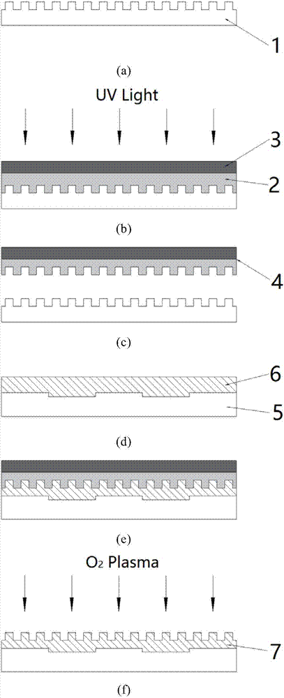
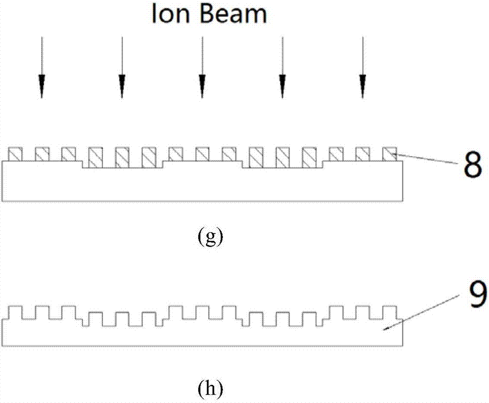
[0037] (1) In size 100×100mm 2 A photoresist was spin-coated on a fused silica substrate with a thickness of 200 nm. Then using Kr with a wavelength of 413.1nm + Ion laser is used for holographic exposure to obtain a sub-wavelength grating photoresist mask with a line density of 4500lines / mm and a duty ratio of 0.3 to 0.5, and then use CHF 3 Reactive ion beam etching with a depth of 150nm, and finally cleaning to remove residual photoresist to obtain a subwavelength grating template 1, such as figure 2 In (a) shown.

[0038] (2) After cleaning the sub-wavelength grating template 1, drop polyurethane acrylate (PUA) UV imprinting glue 2 on it, and then let it stand for PUA to fill the template. fill template. Then cover the polyethylene terephthalate (PET) film 3 on the PUA, a...

Embodiment 2

[0045] Embodiment 2: this specific implementation mode is to make size be 430 * 430mm 2 The anti-reflection beam sampling grating adopts the method of splicing small gratings to realize a large-size anti-reflection grating.

[0046] (1) First make a size of 100×100mm 2 The sub-wavelength grating soft mold 4, this step is the same as the steps (1)-(3) in the embodiment 1, see the splicing method image 3 , using a 4×4 grid, so a total of 16 sub-wavelength grating soft molds need to be repeatedly produced.

[0047] (2) The size is 430×430mm 2 Spin-coat the PMMA embossing glue with a thickness of 250nm on the beam sampling grating 10, and then press image 3 In the splicing method shown, 16 sub-wavelength grating soft molds are embossed, and after heating and curing, the mold is released to obtain a large-size PMMA sub-wavelength grating mask.

[0048] (3) Use the oxygen plasma ashing method to remove the residual PMMA imprinting glue at the bottom. Due to the large size of t...


PUM


Abstract

The invention provides an anti-reflection method for a beam sampling grating in an intense laser system. The method comprises the following steps: to begin with, preparing a sub-wavelength grating template on a fused quartz substrate through a holographic ion beam etching method; dropping a little PUA UV imprinting photoresist on the sub-wavelength grating template, and then, covering a PET film on the PUA; curing the PUA through UV irradiation, and separating the cured PUA from the grating template to obtain a sub-wavelength grating soft template; clearing the surface of the beam sampling grating, and then, spin coating PMMA imprinting photoresist on the surface; covering the sub-wavelength grating soft template on the PMMA, wherein soft template grating fringe direction can be parallel, vertical or form angle with the fringe direction of the beam sampling grating; clamping the two through a clamping mechanism and placing the two into a baking oven for heating and curing; separating the sub-wavelength grating soft template from the substrate, and forming a sub-wavelength grating on the PMMA; then, removing bottom residual photoresist of the PMMA grating through oxygen plasma ashing; by utilizing a to-the-bottom PMMA subwavelength grating mask, carrying out CHF3 reaction ion beam etching; and finally, carrying out cleaning to remove residual photoresist to obtain the beam sampling grating having an anti-reflection effect.

Description

technical field [0001] The invention relates to an anti-reflection and anti-reflection method for the surface of an optical element, in particular to an anti-reflection and anti-reflection method for the grating surface of a light beam sampling grating in a strong laser system. Background technique [0002] Beam sampling gratings are a type of optical element used in powerful laser systems to diagnose the energy, power, and spatial distribution of incident beams. For the diagnostic incident wavelength of 351nm, the -1 order diffracted light is focused on the surface of the light intensity detector, and the diffraction efficiency is about 0.2%. The relevant characteristics of the incident light are calculated from the detector measurement results. [0003] In a strong laser system, a large number of optical components need to be used. Therefore, in this complex optical system, the reflection of the beam on the surface of the optical component cannot be ignored, which directly...

Claims


Application Information

Patent Timeline
IPC IPC(8): G02B5/18G02B1/118
CPCG02B1/118G02B5/1814G02B5/1857
Inventor 陈火耀刘颖梁举曦王宇刘正坤邱克强徐向东洪义麟付绍军
Owner UNIV OF SCI & TECH OF CHINA
Why Eureka
Try Eureka