
Conical spring type high efficiency energy-saving furnace and using method thereof

A high-efficiency energy-saving, tower spring technology, applied in wellhead heating and crude oil transportation in the petroleum industry, can solve the problems of poor heating effect, slow heating, large heat loss, etc., to achieve improved heating efficiency, small furnace volume, The effect of reducing clogging

Inactive Publication Date: 2017-08-11
东营市鑫聚合石油科技有限责任公司 +1
View PDF5 Cites 0 Cited by
  • Summary
  • Abstract
  • Description
  • Claims
  • Application Information

AI Technical Summary

Problems solved by technology

Under the influence of poor physical properties of crude oil and long oil pipelines, many oil wells need to heat the wellhead to reduce the viscosity of crude oil to achieve the purpose of normal oil delivery. At present, most oil wells use a single-well mainline heating furnace with a rectangular cement pouring structure. , because the main line furnace is straight-through heating and has a large internal space, under the normal air source, there will be a problem of large heat loss and slow heating during heating. It will cause a series of problems such as oil well back pressure, high plugging pipeline, etc., which seriously affects the normal production of oil well.

Method used


Image

  • Conical spring type high efficiency energy-saving furnace and using method thereof
  • Conical spring type high efficiency energy-saving furnace and using method thereof

Examples


Embodiment 1

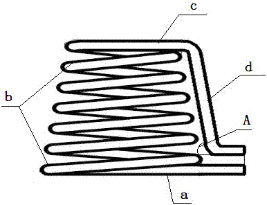
[0015] The present invention includes a chimney 1, a suspension ring 2, a shell 3, a flange 4, a furnace shell 5, an annular bracket 6, a fire starter 7, a gas furnace 8, a ventilation plate 9, and a damper 10. The top of the furnace shell 5 passes through the flange 4 The shell 3 is connected with bolts, the top of the shell 3 communicates with the chimney 1 in the middle, the upper end surface of the shell 3 is symmetrically provided with two lifting rings 2, and the inside of the furnace shell 5 is provided with a ring-shaped bracket 6, The tower spring heating coil 11 is fixed on the annular support 6, and the bottom of the annular support 6 is provided with an ignition device 7 and a gas furnace 8. The ignition device 7 is located at the top of the gas furnace 8, and the inlet of the tower spring heating coil 11 And the outlet extends to the outside of the furnace shell 5, the gas furnace 8 is fixed on the ventilation plate 9 inside the furnace shell 5, the ventilation pla...


PUM


Abstract

The invention relates to a conical spring type high efficiency energy-saving furnace and a using method thereof. The technical scheme lies in that the conical spring type high efficiency energy-saving furnace comprises a chimney, lifting rings, a housing, a flange, a furnace shell, an annular support, an igniter, a gas burner, a ventilating board and an air door, wherein the top of the furnace shell is connected with the housing through the flange and bolts; the middle at the top of the housing is communicated with the chimney; the two lifting rings are arranged on the upper end surface of the housing in a symmetric manner; the annular support is arranged in the furnace shell; a conical spring heating coil is fixed on the annular support; the igniter and the gas burner are arranged at the lower part of the annular support; the igniter is positioned at the upper part of the gas burner; the inlet and the outlet of the conical spring heating coil extend out of the furnace shell; the gas burner is fixed on the ventilating board in the furnace shell; ventilation holes are formed in the ventilating board; the air door is arranged on one side of the bottom of the furnace shell. The conical spring type high efficiency energy-saving furnace and the using method thereof have the benefits as follows: a cylindrical steel structure is adopted, the furnace body is small in size, and the gas consumption is low; besides, the heating coil takes the shape of a conical spring, the heating points are concentrated, the heating coil is free from welding points, and the heat efficiency is high.

Description

technical field [0001] The invention relates to crude oil transportation and wellhead heating in the petroleum industry, in particular to a tower spring type high-efficiency energy-saving furnace and its use method. Background technique [0002] In the process of oil recovery and production, single well trunk heating furnace is an important heating facility in the process of oil well transportation. Under the influence of poor physical properties of crude oil and long oil pipelines, many oil wells need to heat the wellhead to reduce the viscosity of crude oil to achieve the purpose of normal oil delivery. At present, most oil wells use a single-well mainline heating furnace with a rectangular cement pouring structure. , because the main line furnace is straight-through heating and has a large internal space, under the normal air source, there will be a problem of large heat loss and slow heating during heating. It will cause a series of problems such as oil well back pressu...

Claims


Application Information

Patent Timeline
IPC IPC(8): F24H1/16F24H9/18F24H9/00E21B36/02
CPCF24H1/165E21B36/025F24H9/0005F24H9/1836
Inventor 王学强王丹丹赵培杰张建军兰华政胡勇军
Owner 东营市鑫聚合石油科技有限责任公司
Learn More