
Heat radiation material, heat radiation structure, controller and electric tool

A heat dissipation material and heat dissipation structure technology, which is applied in the direction of electrical components, electrical equipment structural parts, cooling/ventilation/heating transformation, etc., can solve the heat dissipation performance deviation of the heat dissipation shell, increase the volume of the heat dissipation shell, reduce the heat dissipation effect, etc. problem, achieve the effect of reducing material cost, high production efficiency and reducing processing

Active Publication Date: 2017-08-08
CHANGSHA QIKE ELECTRONICS
View PDF5 Cites 0 Cited by
  • Summary
  • Abstract
  • Description
  • Claims
  • Application Information

AI Technical Summary

Problems solved by technology

Commonly used materials for heat dissipation shells include Japanese standard ADC12, national standard YL102 or European standard AlSi10Mg, etc. Although the silicon contained in these materials improves the fluidity of aluminum, the fluidity of aluminum will also reduce the heat dissipation effect. Among them The high thermal conductivity is 121W / (m.K), and the lower one is only 92W / (m.K). Therefore, the overall heat dissipation performance of the existing heat dissipation shell is deviated, and larger heat dissipation teeth are required to meet the heat dissipation requirements. However, this It will increase the volume of the heat dissipation shell, take up space, and increase the production cost

Method used


Image

  • Heat radiation material, heat radiation structure, controller and electric tool
  • Heat radiation material, heat radiation structure, controller and electric tool

Examples


Embodiment 1

[0031] A heat dissipation material, the mass percentage of each component in the heat dissipation material is: 80% aluminum alloy, 20% pure aluminum.

[0032] The aluminum alloy is ADC12 aluminum alloy, the mass percentage of each component in the aluminum alloy is: silicon 12%, copper 2.5%, magnesium 0.2%, zinc 1.0%, iron 1.2%, manganese 0.5%, nickel 0.4%, tin 0.3% , calcium 200ppm, lead 0.1%, cadmium 0.005%, the rest is aluminum and unavoidable trace impurities.

Embodiment 2

[0034] A heat dissipation material, the mass percentage of each component in the heat dissipation material is: aluminum alloy 85%, pure aluminum 15%.

[0035] The aluminum alloy is YL102 aluminum alloy. The mass percentage of each component in the aluminum alloy is: 10% silicon, 0.6% copper, 0.5% manganese, 0.05% magnesium, 1.1% iron, 0.3% zinc, and the rest is aluminum and unavoidable Trace impurities.

Embodiment 3

[0037] A heat dissipation material, the mass percentage of each component in the heat dissipation material is: aluminum alloy 75%, pure aluminum 25%.

[0038] The aluminum alloy is A383 aluminum alloy, the mass percentage of each component in the aluminum alloy is: silicon 11.5%, copper 2%, manganese 0.4%, magnesium 0.1%, iron 1.2%, nickel 0.3%, zinc 2%, tin 0.1% , the rest is aluminum and unavoidable trace impurities.


PUM

PropertyMeasurementUnit
thicknessaaaaaaaaaa
heightaaaaaaaaaa
heightaaaaaaaaaa

Abstract

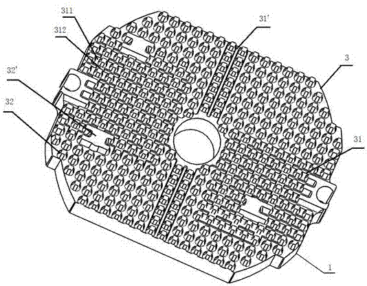
The invention relates to a heat radiation material, a heat radiation structure, a controller and an electric tool. The heat radiation material is prepared from the components in percentage by mass: 70 percent to 95 percent of aluminum alloy, and 5 percent to 30 percent of pure aluminum, wherein the mass percent of silicon contained in the aluminum alloy is 6 percent to 15 percent. The invention also comprises a heat radiation structure, a controller and an electric tool. The heat radiation material provided by the invention not only ensures better liquid-state fluidity, but also has a higher heat conductivity coefficient, and compared with an existing heat radiation shell, under the condition of the same volume, a heat radiation effect of a heat radiation shell provided by the invention is more remarkable compared with the prior art; under the condition of the same heat radiation effect, the volume of the heat radiation shell provided by the invention is smaller compared with the prior art; in addition, the raw materials are less, so that the processing cost and the material cost are greatly reduced.

Description

technical field [0001] The invention relates to the technical field of heat dissipation, in particular to a heat dissipation material, a heat dissipation structure, a controller and an electric tool. Background technique [0002] The heat dissipation shell is mainly produced by high-speed die-casting (die-casting for short). The size of the heat dissipation teeth and the wall is relatively thick. Generally, for the heat dissipation teeth with a height of more than 40mm, the thickness of the tooth top is more than 1.6mm, because it is heavy. Commonly used materials for heat dissipation shells include Japanese standard ADC12, national standard YL102 or European standard AlSi10Mg, etc. Although the silicon contained in these materials improves the fluidity of aluminum, the fluidity of aluminum will also reduce the heat dissipation effect. Among them The high thermal conductivity is 121W / (m.K), and the lower one is only 92W / (m.K). Therefore, the overall heat dissipation performa...

Claims


Application Information

Patent Timeline
Patent Type & Authority Applications(China)
IPC IPC(8): C22C21/02H05K7/20
CPCC22C21/02H05K7/20481
Inventor 綦锋
Owner CHANGSHA QIKE ELECTRONICS
Learn More