
A suspended surface light source for satellite optical payload testing

A technology of load testing and surface light source, which is applied in the direction of optical instrument testing, testing of optical performance, testing of machine/structural components, etc., can solve the problems of whole star security threats, inconvenient test application, large weight and size, etc., and achieve strong promotion value, avoid physical impact damage, cost controllable effect

Active Publication Date: 2019-03-26
AEROSPACE DONGFANGHONG SATELLITE
View PDF7 Cites 0 Cited by
  • Summary
  • Abstract
  • Description
  • Claims
  • Application Information

AI Technical Summary

Problems solved by technology

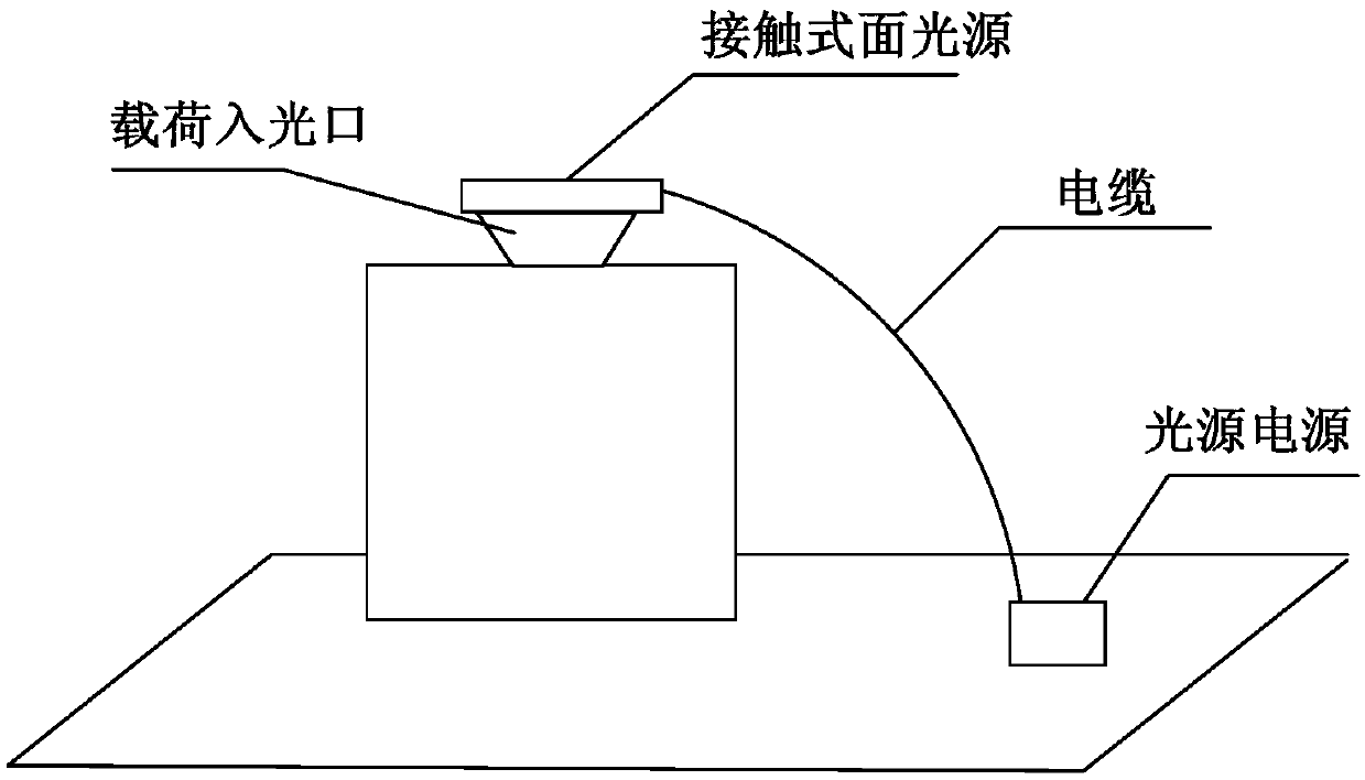
For the second type of load form, there are two commonly used surface light sources: one is the contact type, where the light source is placed directly at the light entrance of the load, see image 3 , the disadvantage of this device is that since the surface light source needs to be in direct contact with the entire star, it is necessary to consider the weight of the light source on the entire star cabin and the load-bearing limit, and at the same time it is necessary to consider the safety hazard of the light source power supply to the entire star power supply. The second is non-contact. The light source is placed on the shelf, the shelf and the light source are not in contact with the whole star, and the four corners of the shelf are placed on the ground, see Figure 4 , the disadvantage of this device is that the final assembly of the whole star test stage requires a safe distance of 2m between the bracket equipment and the whole star. At the same time, considering that the light source is placed on the top of the shelf, the material of the shelf must maintain sufficient strength, so the weight and size of the stand are relatively large, similar to Gantry cranes or cantilever beams are not convenient for testing applications, and there is a hidden danger of the bracket toppling over, which poses a threat to the safety of the entire star
Both of the above two surface light sources need to be installed, which is inconvenient to use

Method used


Image

  • A suspended surface light source for satellite optical payload testing
  • A suspended surface light source for satellite optical payload testing
  • A suspended surface light source for satellite optical payload testing

Examples


Embodiment Construction

[0036] The present invention will be further described in detail below in conjunction with the accompanying drawings and specific embodiments.

[0037] Generally, the direction of the light entrance of the satellite optical load generally refers to the vertical upward direction. To test it, it is necessary to arrange a surface light source above the light entrance of the load. The invention provides a suspended surface light source for satellite optical load test, such as Figure 5 As shown, the suspended surface light source includes a bracket 2, a surface light source power supply 4, a surface light source 3, 8 unmanned aerial vehicles 1, an unmanned aerial vehicle console 5, a hovering monitoring device 6 and a shock-absorbing spacer 7, and the surface light source supplies power. The power supply, the surface light source 3, the shock-absorbing spacer, the unmanned aerial vehicle 1 and the hovering monitoring device are all fixed on the support 2, wherein the surface light...


PUM


Abstract

The invention discloses a suspended area light source for a satellite optical load test. According to the suspended area light source, the area light source is imaged above a load in a suspended manner by employing unmanned aerial vehicles so that problems that weight limitation of a contact type area light source and the power supply safety are avoided, and hidden risks due to falling of a support of a non-contact metal support area light source are avoided; the safety state and the stability of the area light source support are monitored in real time by employing a hovering monitoring device so that when dangers occur, an alarm is emitted or emergency shutdown measures are taken, and the reliability is greatly improved; damping isolation gaskets are configured so that the area light source support can elastically fall on a satellite cabin plate when falling in an abnormal way, and the physical impact damage to the whole satellite and load equipment can be avoided; and the installation of the equipment structure is simple, the universality is high, the power supply mode does no safety harm to the whole satellite, and the operability and the promotion value are high.

Description

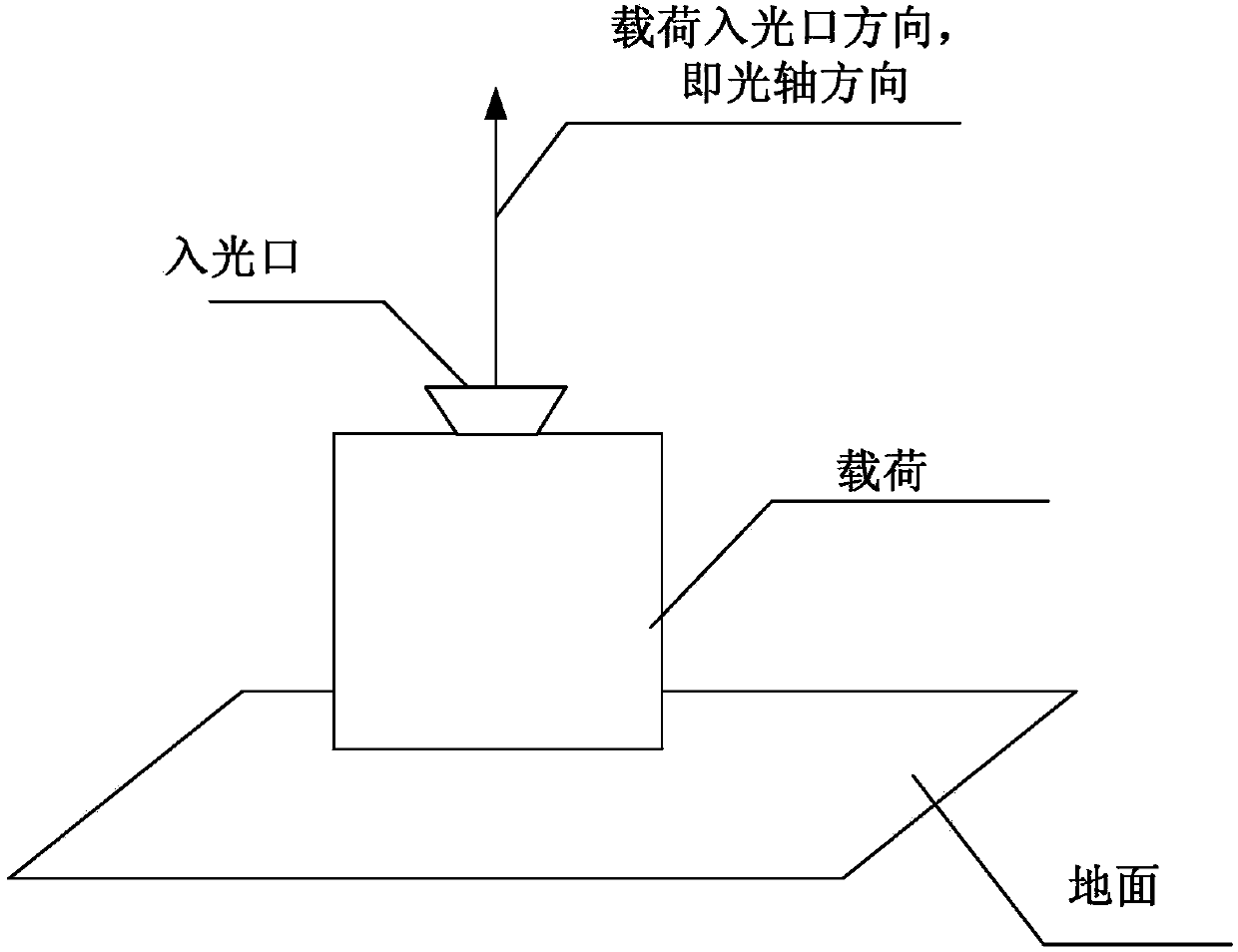
technical field [0001] The invention relates to a suspended surface light source for satellite optical load testing, which is particularly suitable for the imaging load testing of the equipment under test whose load light inlet is vertically upward in the ground testing phase of the satellite, and belongs to the field of satellite testing equipment. Background technique [0002] According to the mission and configuration design, after a type of optical imaging payload is installed on the ground, the light entrance of the payload, that is, the optical axis of the payload, is parallel to the ground, see figure 1 , after a type of optical imaging payload is installed on the ground, the light inlet of the payload, that is, the optical axis of the payload is perpendicular to the ground and upwards, see figure 2 . During the whole-star test, it is necessary to provide a surface light source for the optical imaging load as the light source input for qualitative analysis. For the ...

Claims


Application Information

Patent Timeline
Patent Type & Authority Patents(China)
IPC IPC(8): G01M11/02G01D21/02G05D1/10
CPCG01D21/02G01M11/0214G05D1/101
Inventor 王超叶钊武斌赵鸿志张可立朱军
Owner AEROSPACE DONGFANGHONG SATELLITE
Learn More