Pollution discharge valve for nuclear island
A blowdown valve and nuclear island technology, applied in the field of blowdown valves for nuclear islands, can solve problems such as secondary circuit water loss and achieve good protection effects
- Summary
- Abstract
- Description
- Claims
- Application Information
AI Technical Summary
Problems solved by technology
Method used
Image
Examples
Embodiment 1
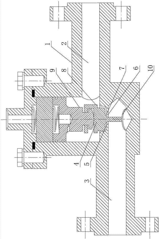
[0025] Such as figure 1 As shown, a blowdown valve for a nuclear island includes a valve seat 1 and a valve core 4 arranged on the valve seat 1. The valve seat 1 is provided with an inlet hole 2 and an outlet hole 3, and the inlet hole 2 and the outlet hole 3 are There is a communication hole 6 between them, the communication hole 6 is provided with a sealing section 5, and the valve core 4 is also connected with a driving part 9 for driving the valve core 4 to move, and the sealing section 5 is arranged in the communication hole The tapered hole on the 6, the part used to cooperate with the sealing section 5 on the valve core 4 is a tapered section 7, and the larger end of the tapered hole is facing the inlet end of the communication hole 6;
[0026] The valve core 4 is hingedly connected to the driving part 9 through a joint bearing, and the center of the spherical surface on the joint bearing falls on the axis of the valve core 4 .
[0027] Specifically, the above driving ...
Embodiment 2
[0029] Such as figure 1 As shown, this embodiment is further limited on the basis of Embodiment 1: the valve core 4 is also provided with an annular boss 8, the boss 8 is facing the inlet end of the communication hole 6, and the boss 8 8 is located outside the inlet end of the communication hole 6, and the projection of the communication hole 6 toward the boss 8 falls within the edge of the boss 8;
[0030] The distance between the boss 8 and the communication hole 6 is less than or equal to the distance between the sealing section 5 and the valve core 4;
[0031] The diameter of the inlet end of the communication hole 6 is larger than the diameter of the sealing section 5 .
[0032] In the prior art, the blowdown valve of the nuclear reactor evaporator mostly adopts a stop valve. In this way, when the blowdown valve installed at the bottom of the secondary circuit water is working, the particulate impurities in the secondary circuit water will block the sealing surface durin...
Embodiment 3
[0038] Such as figure 1 As shown, this embodiment is further limited on the basis of any one of the technical solutions provided by any one of the above embodiments: in order to facilitate the connection between the drain valve and the pipe sections on both sides, and at the same time ensure the reliability of the sealing of the connection surface, it is also included. There are two connecting flanges on the valve seat 1, the inlet end of the inlet hole 2 and the outlet end of the outlet hole 3 are respectively connected with a connecting flange, and the sealing surfaces on the connecting flanges are all tongue and groove surfaces.
[0039] In order to prevent the valve core 4 from vibrating too strongly under the action of the fluid when the drain valve is open, it also includes an elastic sheet 10 fixed on the valve seat 1 , and the free end of the valve core 4 is fixed on the elastic sheet 10 .
PUM
 Abstract
Description
Claims
Application Information
 - Generate Ideas
- Intellectual Property
- Life Sciences
- Materials
- Tech Scout
- Unparalleled Data Quality
- Higher Quality Content
- 60% Fewer Hallucinations
Browse by: Latest US Patents, China's latest patents, Technical Efficacy Thesaurus, Application Domain, Technology Topic, Popular Technical Reports.
© 2025 PatSnap. All rights reserved.Legal|Privacy policy|Modern Slavery Act Transparency Statement|Sitemap|About US| Contact US: help@patsnap.com

