power plant

A power plant and electric energy technology, applied in the direction of electrolysis components, electrolysis process, electrical components, etc., can solve the problems of unstable and unpredictable energy output

Inactive Publication Date: 2019-10-29
SIEMENS AG
View PDF7 Cites 0 Cited by
  • Summary
  • Abstract
  • Description
  • Claims
  • Application Information

AI Technical Summary

Problems solved by technology

These power plants produce no exhaust, but in the case of wind and solar energy output is erratic and unpredictable

Method used


Image

  • power plant

Examples


Embodiment Construction

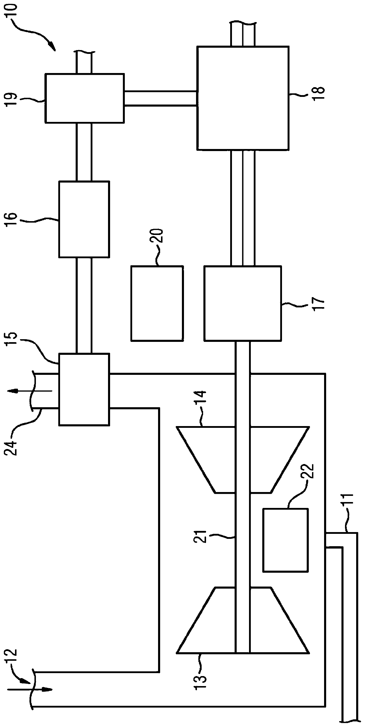
[0023] The drawing shows highly schematically an embodiment of a gas-fired power plant 10 according to the invention. The gas-fired power plant 10 includes a supply line 11 for natural gas, which leads the natural gas to a combustion chamber 22. Also not shown but known are a reservoir area for liquid fuel, for example fuel oil, and a corresponding supply line to the combustion chamber 22.

[0024] The combustion chamber 22 is arranged between the compressor 13 and the turbine 14 provided with the air supply line 12, and the compressor 13 and the turbine 14 are connected to the generator 17 on a common shaft 21. The outlet of the turbine 14 is connected to an exhaust gas outlet pipe 24. The generator 17 is driven by the shaft 21 and is connected to a transformer 18 on the output side, and the transformer 18 is used to supply the generated electric energy to the general power grid.

[0025] The exhaust gas outlet pipe 24 has a carbon dioxide capture device 15, and the carbon dioxi...


PUM


Abstract

A power plant for generating electrical energy comprising: - means for generating electrical energy from fossil fuels, biomass or biogas, - means for extracting and storing carbon dioxide from flue gases produced in the power plant, characterized in consisting in - an electrolysis plant for converting stored carbon dioxide into other substances, - a control device for controlling the electrolysis plant, said control device being designed such that said control device obtains current electricity price data and, when the electricity price falls below When the electricity price threshold is reached, the electrolysis equipment is operated, and when the electricity price exceeds the electricity price threshold, the electrolysis equipment is turned off.

Description

Technical field [0001] The present invention relates to a power plant for generating electricity from fossil fuels, biomass or biogas, which has a device for extracting and storing carbon dioxide from flue gas generated in the power plant, and a method of operating such a power plant. Background technique [0002] Traditional power plants burn fossil fuels, such as coal, to produce electrical energy, namely electricity. The focus of the construction of the power plant is to operate as efficiently as possible, so as to minimize the amount of waste gas containing the greenhouse gas carbon dioxide produced at a given power. However, a large amount of carbon dioxide is generated during operation, and a solution to this problem needs to be found. [0003] In a so-called carbon capture and storage (CCS) method, carbon dioxide is captured and pumped, for example, to storage points underground for ultimate environmentally sustainable storage. However, the energy consumption required for ...

Claims


Application Information

Patent Timeline
Patent Type & Authority Patents(China)
IPC IPC(8): C25B3/04C25B15/02B01D53/62F01K13/00H02J3/28B01D53/14C25B3/25
CPCB01D53/14B01D53/62C25B15/02F01K13/00H02J3/28C25B3/25H02J2300/28H02J3/381H02J3/46B01D53/1425B01D53/1475F01K23/10H02J3/008Y02E20/16Y04S50/10B01D53/965B01D2257/504H02J2300/20Y02C20/40Y02E20/32Y02P80/20B01D53/22B01D2256/22
Inventor M.弗莱舍M.温霍尔德
Owner SIEMENS AG
Why Eureka
Try Eureka