
Underground mixed-phase thermal fluid generator and using method thereof

A technology of thermal fluid and generator, applied in the field of downhole miscible thermal fluid generator, can solve the problems of large environmental pollution, large heat loss, melting of gas hydration layer, etc., to reduce environmental pollution, reduce heat loss, and increase fluidity Effect

Inactive Publication Date: 2017-08-01
DALIAN DONGYOU RUIJIA PETROLEUM TECH CO LTD
View PDF7 Cites 4 Cited by
  • Summary
  • Abstract
  • Description
  • Claims
  • Application Information

AI Technical Summary

Problems solved by technology

Its heat loss mainly includes: the heat loss from steam station boiler and chimney discharge accounts for about 20%, and the heat loss from steam station to wellhead accounts for about 3%-20% (average 13%). Heat insulation measures, the heat loss from the wellhead to the oil layer during steam injection accounts for about 30%-40%, resulting in a huge waste of energy; in order to reduce environmental pollution and heat loss from the wellhead to the oil layer, the US petroleum industry stipulates that Above 2500 feet (762 meters) are not allowed to use the above methods; but 95% of the world's heavy oil reserves are below 2500 feet underground; therefore, the traditional steam stimulation and steam flooding methods have great limitations on the recovery of heavy oil sex
[0004] 2. Mining depth is limited
Due to the relatively large heat loss during the steam injection process, the surface steam injection thermal recovery technology is limited in depth. As the depth of the oil layer increases, the dryness of the steam injected into the oil layer decreases. Due to the heat loss in the oil layer, it has been converted into hot water, which greatly increases the difficulty of steam injection oil recovery
[0005] 3. Long mining cycle
The cycle of a borehole with steam stimulation is usually 2-7 days, and the whole production cycle is about 15 days, and continuous production is not possible, and repeated steam injection into the borehole is required, and the production efficiency is not high; although steam flooding can carry out continuous production, but The cycle of injecting steam is still longer
[0006] 4. Poor mobility of the whole device
The installation of the steam station boiler needs to build an installation foundation on the ground. It is difficult to move the steam station boiler after it is established. Due to the huge steam generation equipment on the ground, the application in offshore oil fields and some well sites with limited margins is limited, so it is difficult to adapt to different oil field sites. requirements
[0007] 5. Serious environmental pollution
The flue gas emitted by boilers in steam stations contains a large amount of pollutants such as sulfides, nitrogen oxides, and particulate matter, which will not only cause a large amount of heat loss, but also cause great environmental pollution
[0008] 6. Hidden danger of shaft collapse
Part of the formation contains permafrost between the surface and the oil layer, or the oil layer is on the seabed with a lower temperature. The hot gas injected from the surface may increase the temperature of the casing and the outer wall of the casing, resulting in permafrost. Melts or melts gas hydration layers in seafloor sediments, causing the formation to expand at the melted site, possibly leading to wellbore collapse

Method used


Image

  • Underground mixed-phase thermal fluid generator and using method thereof
  • Underground mixed-phase thermal fluid generator and using method thereof
  • Underground mixed-phase thermal fluid generator and using method thereof

Examples


Embodiment Construction

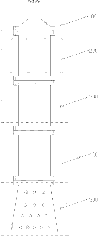
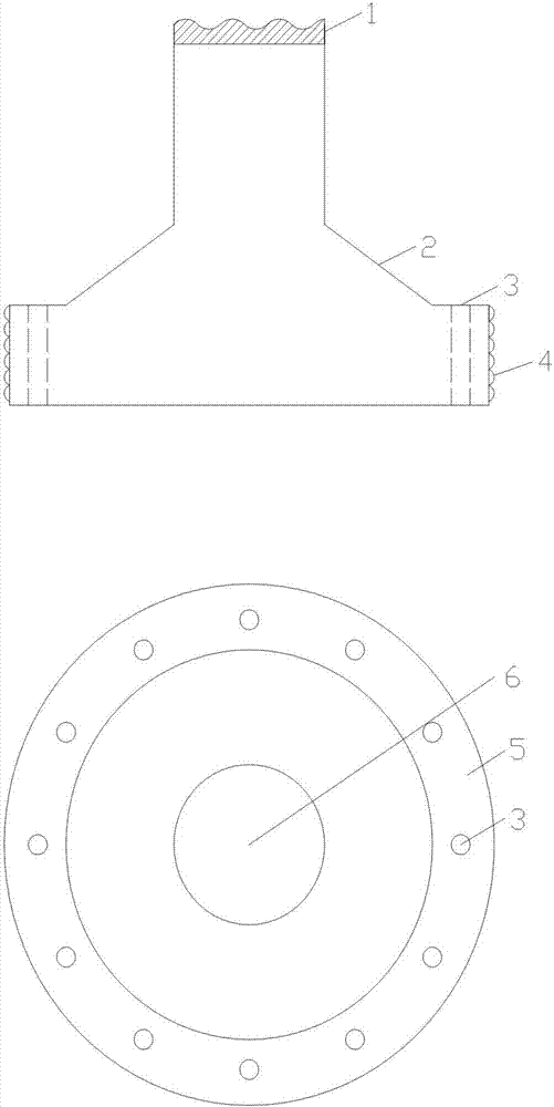
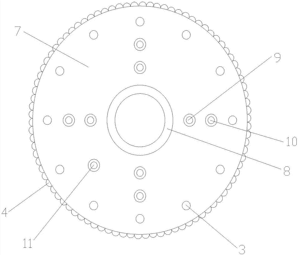
[0026] figure 1 It is a schematic diagram of the structure of the downhole miscible thermal fluid generator. The downhole mixed-phase thermal fluid generator includes a top connection assembly 100 , a combustion assembly 200 , a vaporization assembly 300 , a screw pressurization assembly 400 and an injection assembly 500 . The top connection assembly 100 is connected to the upper part of the combustion assembly 200 by bolts, the vaporization assembly 300 is connected to the lower part of the combustion assembly 200 by bolts, the screw booster assembly 400 is connected to the lower part of the vaporization assembly 300 by bolts, and the injection assembly 500 is connected to the screw booster assembly by bolts 400 lower part; the outer diameter of the connection of the top connection assembly 100, the combustion assembly 200, the vaporization assembly 300, the screw pressurization assembly 400 and the injection assembly 500 is defined by the inner diameter of the oil well casin...


PUM


Abstract

The invention discloses an underground mixed-phase thermal fluid generator and a using method thereof, and relates to the field of the oil and gas extraction. The underground mixed-phase thermal fluid generator comprises a top connecting component, a burning component, a vaporizing component, a spiral pressurizing component and a spraying component. The using method comprises the following steps: supplying one or more types of fluid to the generator, forming a combustion product through the combustion of an internal fuel and an oxidizing agent, spraying water into the combustion product to form the mixed-phase thermal fluid, injecting the mixed-phase thermal fluid into oil deposit through the spiral pressurizing component and the spraying component so as to improve the extraction rate of the crude oil and the natural gas. The underground mixed-phase thermal fluid generator has the characteristics of simple application and strong adaptability, and can be applied for primary oil recovery or tertiary oil recovery of the thickened oil and super thickened oil deposit hardly extracted by the traditional oil extraction method.

Description

technical field [0001] The invention relates to a downhole mixed-phase thermal fluid generator and a use method thereof, which relate to the field of oil and gas exploitation. Background technique [0002] At present, the technology for mining heavy oil is mainly thermal extraction, and the thermal extraction methods mainly include steam huff and puff and steam flooding. Both of these methods require the construction of steam station boilers on the ground, and the high-temperature and high-pressure steam is input into the underground through pipelines to extract high-viscosity underground oil. The main disadvantages of these two methods are: [0003] 1. Large heat loss. Its heat loss mainly includes: the heat loss from steam station boiler and chimney discharge accounts for about 20%, and the heat loss from steam station to wellhead accounts for about 3%-20% (average 13%). Heat insulation measures, the heat loss from the wellhead to the oil layer during steam injection ac...

Claims


Application Information

Patent Timeline
Patent Type & Authority Applications(China)
IPC IPC(8): E21B43/243F22B1/22
CPCE21B43/243F22B1/22
Inventor 袁鹏飞张晓丽
Owner DALIAN DONGYOU RUIJIA PETROLEUM TECH CO LTD
Learn More