Method and apparatus of determining point location of well and well depth through micro-logging in complicated surface region

A technology with complex surface and definite method, which is applied in the field of micro-logging, can solve the problems of not being able to obtain the thickness and velocity of high-speed layer velocity weathered layer, not being able to realize surface survey, and not being able to carry out the process, so as to avoid blindness, improve efficiency, and improve The effect of accuracy

Active Publication Date: 2017-07-28
BC P INC CHINA NAT PETROLEUM CORP +1
View PDF7 Cites 12 Cited by
  • Summary
  • Abstract
  • Description
  • Claims
  • Application Information

AI Technical Summary

Problems solved by technology

However, this layout method has certain disadvantages. If the regolith thickness exceeds the limit of the drilling rig's drilling capability within a large area of ​​the same surface lithology, if the micro-logging survey is still carried out according to the regular density, then the area between Every micro-logging survey in the country cannot obtain the required high-speed layer velocity and the thickness and velocity of the weathered layer between the top interface and the surface, so the purpose of surface survey cannot be achieved
[0007] Since the surface survey is the first process of seismic acquisition, if this process is not completed, the subsequent processes cannot be carried out

Method used


Image

  • Method and apparatus of determining point location of well and well depth through micro-logging in complicated surface region
  • Method and apparatus of determining point location of well and well depth through micro-logging in complicated surface region
  • Method and apparatus of determining point location of well and well depth through micro-logging in complicated surface region

Examples


Embodiment Construction

[0057] In order to enable those skilled in the art to better understand the technical solutions in the present application, the technical solutions in the embodiments of the present application will be clearly and completely described below in conjunction with the drawings in the embodiments of the present application. Obviously, the described The embodiments are only some of the embodiments of the present application, but not all of them. Based on the embodiments in this application, all other embodiments obtained by persons of ordinary skill in the art without creative efforts shall fall within the scope of protection of this application.

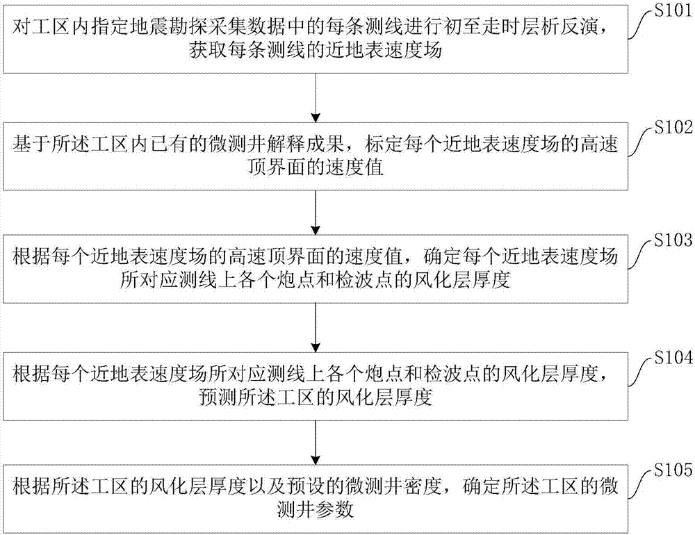
[0058] refer to figure 1 As shown, the method for determining the micro-logging point and well depth in the complex surface area of ​​the embodiment of the present application may include the following steps:

[0059] Step S101 , performing first-arrival travel time tomographic inversion for each survey line in the specified seismic surv...


PUM


Abstract

The embodiment of the invention provides a method and apparatus of determining point location of a well and well depth through micro-logging in a complicated surface region. The method of determining point location of a well and well depth through micro-logging in a complicated surface region includes the steps: performing first-arrival travel time tomographic inversion on each measuring line in the specified seismic prospecting acquisition data in a work region to obtain the near-surface velocity field of each measuring line; based on the existing micro-logging explanation result in the work region, calibrating the velocity amplitude of the high velocity top interface of each near-surface velocity field; according to the velocity amplitude of the high velocity top interface of each near-surface velocity field, determining the weathered layer thickness of each shot point and demodulator probe on the corresponding measuring line of each near-surface velocity field; and according to the weathered layer thickness of each shot point and demodulator probe on the corresponding measuring line of each near-surface velocity field, predicting the weathered layer thickness of the work region; and according to the weathered layer thickness of the work region and the preset micro-logging density, determining the micro-logging parameter of the work region. The method and apparatus of determining point location of a well and well depth through micro-logging in a complicated surface region can improve the surface layer investigation efficiency and reduce the surface layer investigation cost.

Description

technical field [0001] The present application relates to micro-logging technology, in particular to a method and device for determining micro-logging points and well depths in complex surface areas. Background technique [0002] In geophysical prospecting, surface survey is the first procedure in the process of field seismic acquisition, and it is also an essential basic work. The near-surface model obtained by interpolating the interpretation results of the surface survey can provide basic data for the calculation of field statics, the design of the excitation well depth model, and the design of the height difference of the geophone combination, and can also provide data for pre-stack depth migration processing. Accurate near-surface velocity fields. It can be seen that the surface survey process is directly related to all aspects of seismic exploration in the subsequent seismic acquisition process, such as excitation, reception, field processing, and pre-stack depth migr...

Claims


Application Information

Patent Timeline
IPC IPC(8): G01V1/50
CPCG01V1/50G01V2210/6169
Inventor 吕景峰陈学强王乃建祖云飞毛哲巍苏欢欢
Owner BC P INC CHINA NAT PETROLEUM CORP
Why Eureka
Try Eureka