
Track traffic overhead station

A rail transit and station technology, applied in the field of rail transit, can solve the problems of large self-weight load, long road occupation period, complicated construction, etc., to reduce environmental impact, reduce road occupation time, and improve construction quality.

Active Publication Date: 2017-07-28
CHINA RAILWAY ENG CONSULTING GRP CO LTD +1
View PDF10 Cites 13 Cited by
  • Summary
  • Abstract
  • Description
  • Claims
  • Application Information

AI Technical Summary

Problems solved by technology

During a large earthquake, the plastic hinge formed by a single reinforced concrete column has poor ductility, which cannot consume the energy of the structure during vibration, and is prone to irreparable damage. Therefore, the seismic performance of the structure under earthquake is poor.
[0005] 2. The traditional concrete single-column structure adopts the method of on-site pouring, and the construction is complicated. Generally, the following procedures are required: erecting a full hall of scaffolding to pour beam-slab components; supporting formwork to pour beam-column components; binding steel bars, etc.
All the above processes need to be completed on site, resulting in disadvantages such as long construction period, long road occupation period, and difficulty in pouring concrete.
[0006] 3. Due to the large size of the components of the traditional concrete single-column structure, it has a negative impact on the urban landscape
At the same time, the concrete structure will have a great impact and pollution on the surrounding environment during the construction process.
[0007] 4. The traditional concrete single-column structure has a large self-weight load, a large amount of reinforcement for beam-column components, a small clear distance between steel bars, and a large amount of engineering work for binding steel bars, which makes concrete pouring difficult and difficult to control the construction quality

Method used


Image

  • Track traffic overhead station
  • Track traffic overhead station
  • Track traffic overhead station

Examples


Embodiment Construction

[0030] In order to make the object, technical solution and advantages of the present invention clearer, the present invention will be further described in detail below with reference to the accompanying drawings and examples.

[0031] This embodiment provides a rail transit elevated station.

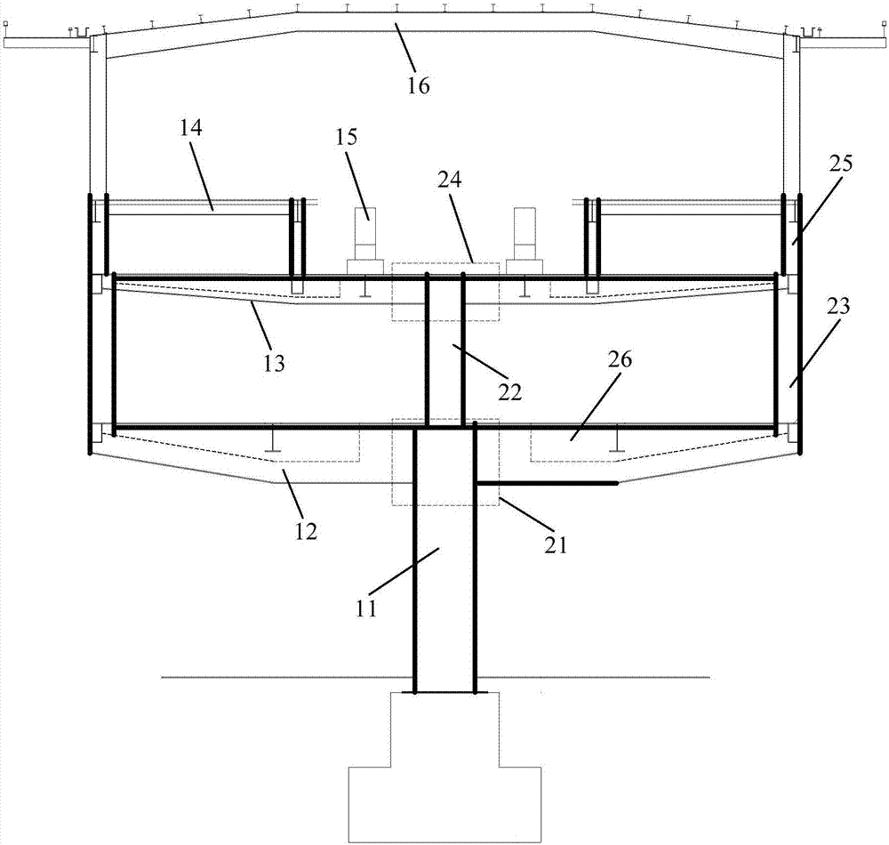
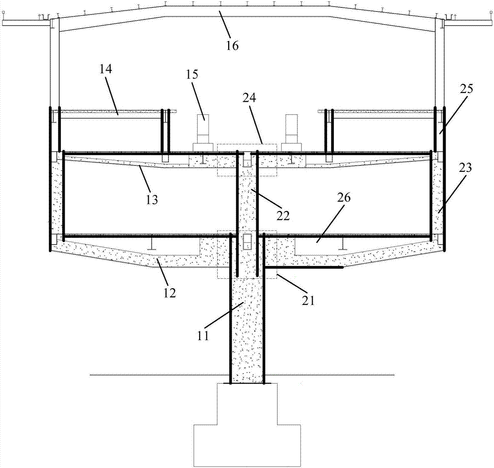
[0032] Figure 1~3 They are respectively a front view, a sectional view and a side view of the rail transit elevated station in the embodiment of the present invention. Such as Figure 1~3 As shown, the rail transit elevated station in the embodiment of the present invention mainly includes: multiple single-column steel-concrete composite frame structures 10;

[0033] Wherein, each single-column steel-concrete composite frame structure includes: pier column 11, first steel-concrete composite beam 12, second steel-concrete composite beam 13, platform structure 14, track beam 15 and roof canopy 16;

[0034] The top of the pier column 11 is equipped with a first combined beam-column node...


PUM


Abstract

The invention discloses a track traffic overhead station. The track traffic overhead station comprises a plurality of single-column steel-concrete combined frame structures, and each single-column steel-concrete combined frame structure comprises a pier column, a first steel-concrete combined beam, a second steel-concrete combined beam, platform structures, track beams and a roof canopy; the first steel-concrete combined beams are mounted at the tops of the pier columns through first combined beam column nodes; the second steel-concrete combined beams are mounted at the tops of a middle column and side columns of a station hall layer through second combined beam column nodes; the roof canopies are mounted at the tops of supporting columns of the two ends of the second steel-concrete combined beams; and the first steel-concrete combined beams and the second steel-concrete combined beams are each a square steel pipe combined beam with a containing cavity, and the bottoms of the containing cavities and the connecting positions of the containing cavities and the first combined beam column nodes or the second combined beam column nodes are poured with concrete. By adoption of the track traffic overhead station, the self weights of structural components can be reduced, structural ductility and seismic performance are improved, and the construction period is shortened.

Description

technical field [0001] The invention relates to rail transit technology, in particular to a rail transit elevated station. Background technique [0002] At present, the elevated stations (side platforms and island platform stations) of domestic rail transit projects adopt a relatively high proportion of single-column structures, and all of them adopt cast-in-place reinforced concrete structures. The advantage of this structure is that the maintenance workload during operation is relatively small, and the engineering cost is relatively low. [0003] However, the above-mentioned rail transit elevated station using traditional concrete single column structure in the prior art also has the following disadvantages: [0004] 1. The traditional concrete single-column structure is self-heavy, the component size is large, the structural volume is large, and the overall lateral force resistance system of the structure has only one single column, which will bear a large axial force an...

Claims


Application Information

Patent Timeline
Patent Type & Authority Applications(China)
IPC IPC(8): E04B1/34
CPCE04B1/3408
Inventor 王永赵卫荣任振国聂建国庄亮东
Owner CHINA RAILWAY ENG CONSULTING GRP CO LTD
Learn More