
Radio frequency switch circuit

A radio frequency switch and circuit technology, applied in circuits, electronic switches, electrical components, etc., can solve problems such as occupation, large chip area, and limiting the maximum input power of radio frequency switches.

Inactive Publication Date: 2017-07-21
GUANGDONG UNIV OF TECH
View PDF5 Cites 12 Cited by
  • Summary
  • Abstract
  • Description
  • Claims
  • Application Information

AI Technical Summary

Problems solved by technology

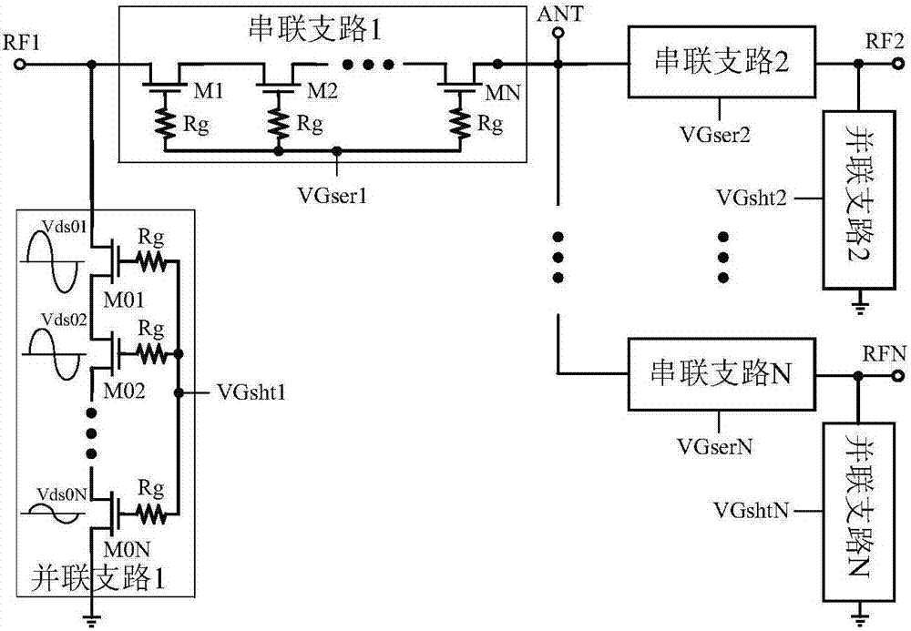
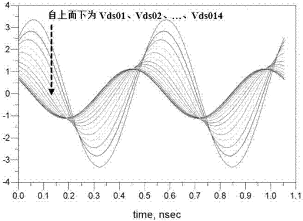
On the one hand, the top transistor will reach the breakdown voltage first, limiting the maximum input power that the RF switch can handle; on the other hand, the MOS transistor with a larger voltage swing will contribute greater higher harmonics, thereby reducing the RF Overall linearity of the switch
The traditional solution is to increase the number of stacked transistors in series and parallel branches, at the cost of greater insertion loss and larger chip area

Method used


Image

  • Radio frequency switch circuit
  • Radio frequency switch circuit
  • Radio frequency switch circuit

Examples


Embodiment Construction

[0032] The following will clearly and completely describe the technical solutions in the embodiments of the present invention with reference to the accompanying drawings in the embodiments of the present invention. Obviously, the described embodiments are only some, not all, embodiments of the present invention. Based on the embodiments of the present invention, all other embodiments obtained by persons of ordinary skill in the art without creative efforts fall within the protection scope of the present invention.

[0033] The embodiment of the present invention discloses a radio frequency switch circuit to improve the power handling capacity and linearity of the switch, and at the same time prevent the MOS transistor at the top of the stacked transistor chain from being broken down first under a large voltage swing, so as to achieve a more reliable RF switch.

[0034] A radio frequency switch circuit provided by an embodiment of the present invention includes a plurality of r...


PUM


Abstract

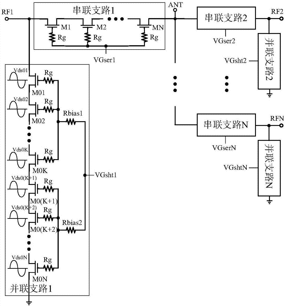
The invention discloses a radio frequency switch circuit. The radio frequency switch circuit comprises a plurality of radio frequency signal pathways; each of the radio frequency signal pathways includes a series branch and a parallel branch; each of the parallel branches includes N stacked MOS FETs; each of the parallel branches further includes N grid parallel resistors respectively connected with grids of the N MOS FETs, and M biasing resistors having certain ends connected with at least one grid parallel resistor and the other ends connected with a parallel control signal. Therefore, the grid parallel resistors in the parallel branch all are connected with the biasing resistors and then are connected to a control signal port together, so the non-uniform distribution of a large voltage swing on each of the stacked MOS FETs can be very effectively improved, and each of the FETs bears the relatively uniform voltage swing; and thus, the FETs on a top end of a stacked-FET chain are prevented from being first broken down, and the worsening of a switching harmonic due to the large voltage swing on the FETs is prevented, thereby further improving the power handling capacity and the linearity of the radio frequency switch.

Description

technical field [0001] The present invention relates to the technical field of radio frequency integrated circuits, and more specifically, relates to a radio frequency switch circuit. Background technique [0002] With the continuous evolution of mobile terminal versions and the adoption of WCDMA and 3GPP LTE standards, the current number of cellular communication operating frequency bands has increased to 14 or 16. To support so many frequency bands and operating modes in mobile small devices, radio frequency (RF) switches play a role. more and more important role, especially the main antenna switch. However, the main antenna switch usually includes GSM and 3G. / 4G and other frequency band channels. It has the largest size, the highest complexity, and the strongest power handling capability. It must have at least +36dBm GSM Tx power capacity. If circuit loss and antenna mismatch are considered , the power handling capability should reach +40dBm (10W). In addition, consider...

Claims


Application Information

Patent Timeline
IPC IPC(8): H03K17/081H03K17/687
CPCH03K17/08104H03K17/687
Inventor 张志浩陈哲章国豪林俊明余凯李思臻刘祖华许洪玮
Owner GUANGDONG UNIV OF TECH
Learn More