High-temperature sealed electrode and preparation method thereof

A high-temperature sealing and electrode technology, which is applied in the direction of sealing materials, circuits, electrical components, etc., can solve the problems of cumbersome assembly process and large battery space, and achieve the effect of compact structure, compressed space volume, and corrosion resistance

Active Publication Date: 2017-07-21
HUAZHONG UNIV OF SCI & TECH +2
View PDF3 Cites 9 Cited by
  • Summary
  • Abstract
  • Description
  • Claims
  • Application Information

AI Technical Summary

Problems solved by technology

[0007] In view of the above defects or improvement needs of the prior art, the present invention provides a high-temperature sealed electrode and a manufacturing method thereof. The high-temperature sealed electrode adopts a salt-sealed structure to prevent steam from eroding the solder, and at the same time, an insulating sleeve is provided on the negative electrode core and the positive electrode cover plate Tubes to prevent the cracking of the sealing electrode connection part caused by thermal stress, and at the same time cooperate with other components to realize the long-term insulation and sealing of liquid metal batteries under high temperature conditions, and solve the problem of excessive battery space volume caused by the existing sealing methods of liquid metal batteries. The problem of cumbersome assembly process

Method used


Image

  • High-temperature sealed electrode and preparation method thereof
  • High-temperature sealed electrode and preparation method thereof
  • High-temperature sealed electrode and preparation method thereof

Examples


Embodiment Construction

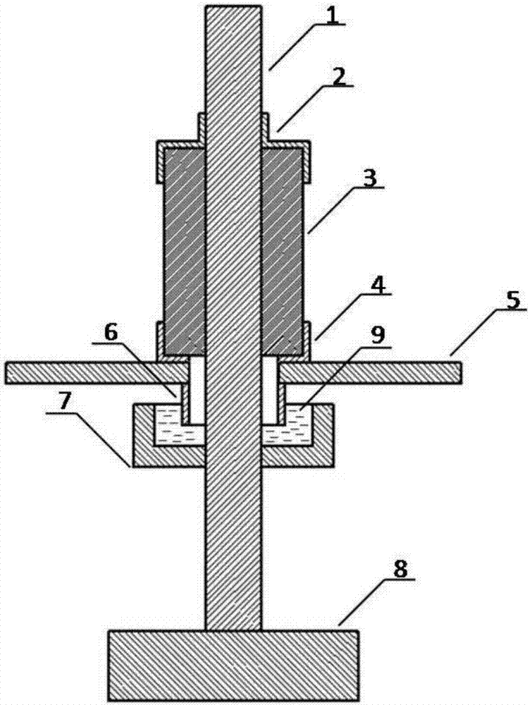
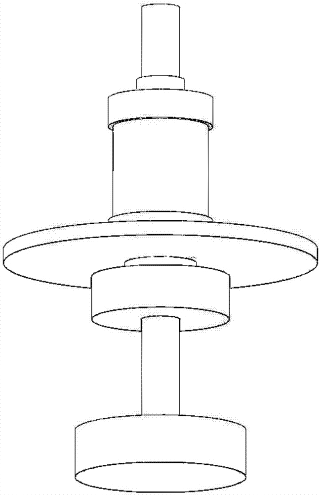
[0032] In order to make the object, technical solution and advantages of the present invention clearer, the present invention will be further described in detail below in conjunction with the accompanying drawings and embodiments. It should be understood that the specific embodiments described here are only used to explain the present invention, not to limit the present invention. In addition, the technical features involved in the various embodiments of the present invention described below can be combined with each other as long as they do not constitute a conflict with each other.

[0033] like figure 1 and figure 2 As shown, it is the high-temperature sealed electrode for liquid metal battery of the present invention, including negative electrode core 1, upper transition ring 2, insulating ceramic sleeve 3, lower transition ring 4, positive electrode cover plate 5, salt seal partition 6, salt seal Tank 7, negative current collector 8, sealing salt 9.

[0034] Among the...


PUM

PropertyMeasurementUnit
thicknessaaaaaaaaaa
heightaaaaaaaaaa
current efficiencyaaaaaaaaaa

Abstract

The invention belongs to the technical field of energy storage batteries and particularly relates to a high-temperature sealed electrode. The high-temperature sealed electrode comprises a negative electrode core, an upper transition ring, an insulating sleeve, a lower transition ring, a positive electrode cover plate, a salt-sealing partition and a salt-sealing groove, wherein the upper transition ring, the insulating sleeve, the lower transition ring, the positive electrode cover plate, the salt-sealing partition and the salt-sealing groove sequentially sleeve the middle of the negative electrode core from top to bottom; a negative current collector is also welded at the bottom of the negative electrode core; the salt-sealing partition is fixed at the lower end of the positive electrode cover plate; the salt-sealing groove is also fixed in the negative electrode core at the lower end of the salt-sealing partition; the lower end of the salt-sealing partition extends into a sealed salt in the salt-sealing groove; and sealing of the electrode is achieved through heating and solidifying the sealed salt. The invention further discloses a preparation method of the high-temperature sealed electrode. According to the high-temperature sealed electrode, corrosion of steam to solder can be prevented, cracking of a connection part of the sealed electrode caused by thermal stress is prevented, long-term insulated sealing in a high-temperature condition is achieved, the sealed electrode is compact in structure and the space volume of a liquid metal battery is effectively compressed.

Description

technical field [0001] The invention belongs to the technical field of energy storage batteries, and more specifically relates to a high-temperature sealed electrode and a manufacturing method thereof. Background technique [0002] Liquid metal batteries are high-temperature batteries, usually working at 300°C to 700°C, the positive and negative electrodes are liquid metal, and the electrolyte is liquid or semi-liquid inorganic molten salt. The positive electrode, electrolyte, and negative electrode materials are automatically layered from bottom to top because they are incompatible with each other. When the battery is working, it is discharged through the formation of a positive electrode alloy between the negative electrode metal and the positive electrode metal; correspondingly, the negative electrode metal and the positive electrode metal are recharged through the electrolysis of the positive electrode alloy (Kim H, Boysen D A, Newhouse J M, et al. LiquidMetal Batteries-...

Claims


Application Information

Patent Timeline
Patent Type & Authority Applications(China)
IPC IPC(8): H01M2/08H01M10/39H01M50/184H01M50/186H01M50/571
CPCH01M10/399H01M50/183Y02E60/10
Inventor 蒋凯彭勃王康丽郭姣姣张坤黎朝晖胡林李侠张玘
Owner HUAZHONG UNIV OF SCI & TECH
Why Eureka
Try Eureka