Laser cutting method and equipment
A laser cutting and equipment technology, applied in laser welding equipment, welding equipment, metal processing equipment and other directions, can solve the problems of three-dimensional space error, reduce product quality, plane translation error, etc., achieve precise control and adjustment, real-time control and adjustment , to ensure the effect of precision
- Summary
- Abstract
- Description
- Claims
- Application Information
AI Technical Summary
Problems solved by technology
Method used
Image
Examples
Embodiment 1
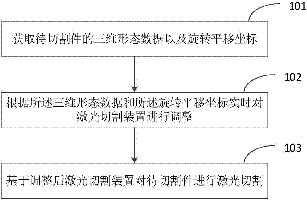
[0050] Embodiment 1 of the present invention discloses a method of laser cutting, such as figure 1 shown, including:
[0051] Step 101, obtaining the three-dimensional shape data and the rotation and translation coordinates of the piece to be cut;
[0052] Step 102, adjusting the laser cutting device in real time according to the three-dimensional shape data and the rotation and translation coordinates;
[0053] Step 103, performing laser cutting on the workpiece to be cut based on the adjusted laser cutting device.
[0054] Specifically, in one embodiment, the "obtaining the three-dimensional shape data and the rotation and translation coordinates of the piece to be cut" described in step 101 includes:
[0055] Directly shoot the surface of the workpiece to be cut at a vertical angle through the linear laser emitting device;
[0056] Extract the laser linear modulation information on the surface of the workpiece to be cut through the area array binocular CCD / CMOS image senso...
Embodiment 2
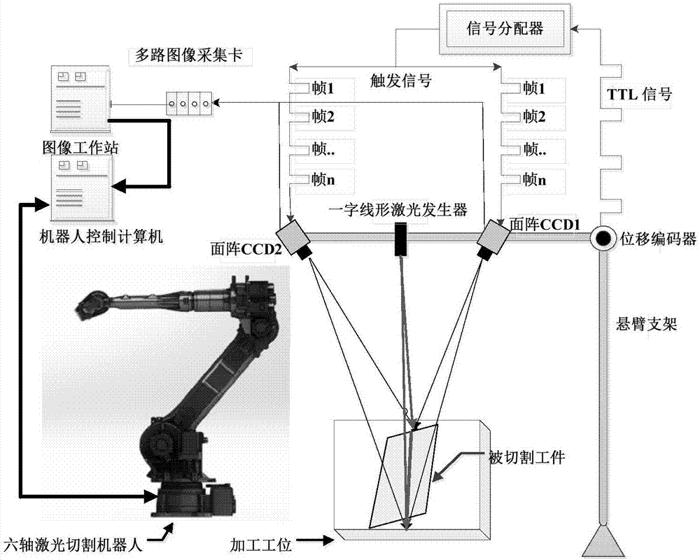
[0066] In order to further illustrate the present invention, the present invention also proposes a specific laser cutting method based on a specific application environment.
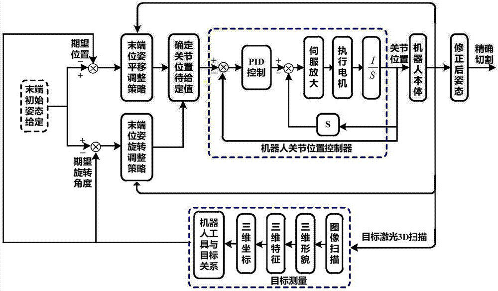
[0067] Such as figure 2 As shown, it is a schematic diagram of a control scheme in this scheme; first, a binocular laser three-dimensional scanning imaging unit is constructed, which is mainly composed of a high-precision non-diffracting linear laser transmitter, a binocular area array CCD / CMOS image sensor, and a mechanical The scanning device is mainly used to complete the shape detection and rotation and translation coordinate extraction of the three-dimensional Cartesian space of the workpiece; in addition, it also includes a robot end tool coordinate correction method that combines three-dimensional scanning imaging and hybrid visual servo control. The translation and rotation coordinate values provided by the test piece are combined with image-based and position-based visual servo control method...
Embodiment 3
[0081] Embodiment 3 of the present invention also discloses a laser cutting device, such as Image 6 shown, including:
[0082] An acquisition module 201, configured to acquire the three-dimensional shape data and the rotation and translation coordinates of the piece to be cut;
[0083] An adjustment module 202, configured to adjust the laser cutting device in real time according to the three-dimensional shape data and the rotation and translation coordinates;
[0084] The cutting module 203 is configured to perform laser cutting on the workpiece to be cut based on the adjusted laser cutting device.
[0085] In a specific embodiment, the acquiring module 201 is configured to:
[0086] Directly shoot the surface of the workpiece to be cut at a vertical angle through the linear laser emitting device;
[0087] Extract the laser linear modulation information on the surface of the workpiece to be cut through the area array binocular CCD / CMOS image sensor, and generate the three-...
PUM
 Abstract
Description
Claims
Application Information
 - R&D
- Intellectual Property
- Life Sciences
- Materials
- Tech Scout
- Unparalleled Data Quality
- Higher Quality Content
- 60% Fewer Hallucinations
Browse by: Latest US Patents, China's latest patents, Technical Efficacy Thesaurus, Application Domain, Technology Topic, Popular Technical Reports.
© 2025 PatSnap. All rights reserved.Legal|Privacy policy|Modern Slavery Act Transparency Statement|Sitemap|About US| Contact US: help@patsnap.com


