
Flip chip type semiconductor packaging structure

A packaging structure, flip-chip technology, applied in the direction of semiconductor devices, semiconductor/solid-state device manufacturing, semiconductor/solid-state device components, etc., can solve problems such as bump cracks, packaging failure, failure, etc., to improve thermo-mechanical reliability. , the effect of dispersion distortion

Inactive Publication Date: 2017-07-18
XIDIAN UNIV
View PDF6 Cites 4 Cited by
  • Summary
  • Abstract
  • Description
  • Claims
  • Application Information

AI Technical Summary

Problems solved by technology

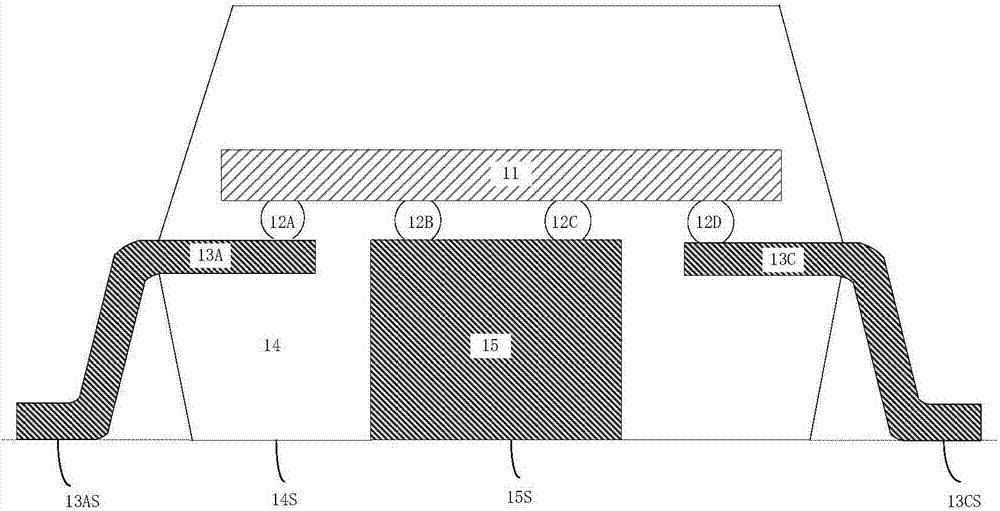
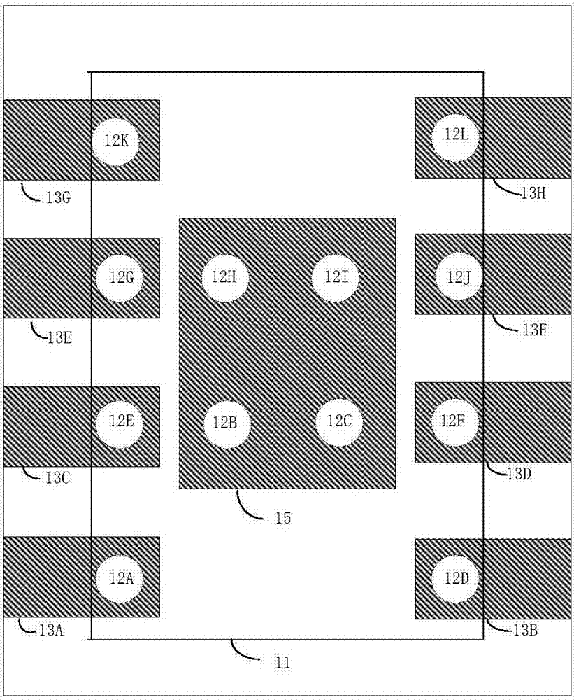
Therefore, the middle area of ​​the main surface of the chip is occupied by the lead frame, and the heat on the chip is conducted to the heat sink through the metal bump to provide a high thermal conductivity channel. Heat is conducted almost exclusively to the lead frame and molding compound
[0007] In addition, in flip-chip packaging, due to the thermal expansion coefficient mismatch between the chip and the lead frame, the bumps on the chip will generate thermal stress and strain, and the accumulated strain energy will cause the bumps to crack and break, resulting in package failure.

Method used


Image

  • Flip chip type semiconductor packaging structure
  • Flip chip type semiconductor packaging structure
  • Flip chip type semiconductor packaging structure

Examples


Embodiment 1

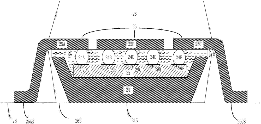
[0023] refer to image 3 , The flip-chip semiconductor packaging structure of the present invention includes: a lead frame 25 , a set of metal bumps 24A- 24E , an integrated circuit chip 23 , a heat sink block 21 and a molding compound 26 .

[0024] Lead frame 25 is provided with several pins that are insulated from each other. In this embodiment, three pins 25A-25C are taken as an example. The main surface of chip 23 is reserved with contact pads, and the contact pads are distributed according to the requirements of chip input and output signals. in the center and peripheral areas of the chip 23. The first metal bump 24A is planted on the chip 23 on the first contact pad 29A close to the first pin 25A, the second metal bump 24B is planted on the chip 23 on the second contact pad 29B close to the first pin 25A, The third metal bump 24C is planted on the third contact pad 29C in the middle area on the chip 23, the fourth metal bump 24D is planted on the fourth contact pad 29D ...

Embodiment 2

[0033] The structural relationship of this embodiment is the same as that of Embodiment 1, the difference is that the shapes of the cooling block and the groove are different, and the shape and structure of the cooling block and the groove are as follows: Figure 4 shown. The shape of the cooling block 31 in this example is a cuboid, and the shape of the groove is a step. The area of ​​the bottom surface 30 in the step groove is smaller than the area of ​​the backside of the chip.


PUM

PropertyMeasurementUnit
Thicknessaaaaaaaaaa
Thermal conductivityaaaaaaaaaa
Volume resistivityaaaaaaaaaa

Abstract

The invention discloses a flip chip type semiconductor packaging structure which comprises an integrated circuit chip (23), a lead frame (25) and a group of metal projections (24A-24E). The group of metal projections is implanted on a surface contact pad which is reserved on the main surface of the integrated circuit chip. The lead frame is provided with a plurality of pins (25A-25C) which are insulated from one another. The pins extend according to an arrangement layout of the metal projections which output the same signal. A heat radiating block (21) with a recessed trough is arranged below the integrated circuit chip. The integrated circuit chip is integrally embedded into the recessed trough and is electrically connected with the lead frame through the metal projections. High-heat-conductivity insulating pouring sealant is filled between the chip and the frame. A directional flip chip type structure in which the main surface of the integrated circuit chip is arranged at the upper part is formed. A molding compound (26) packages the directional flip chip type structure. The flip chip type semiconductor packaging structure improves heat radiating capability and heat reliability of the integrated circuit chip and can be used for packaging a high-power chip and a high-density integrated circuit.

Description

technical field [0001] The invention relates to the technical field of semiconductor packaging, in particular to a flip-chip semiconductor packaging structure, which can be used for packaging high-power chips and high-density integrated circuits. Background technique [0002] Integrated circuit chips generate a lot of heat during operation, and the low thermal conductivity of the molding compound makes it difficult for the encapsulated chip to dissipate heat. Therefore, it is necessary to design its packaging structure to reduce thermal resistance. [0003] In traditional packaging, wire bonding is generally used to electrically connect the chip to the lead frame. This connection method is easy to increase the conduction resistance and thermal resistance between the chip and the lead, and the lead is also easy to break. [0004] Flip-chip packaging is to turn the chip upside down on the lead frame or substrate, and the metal bumps on the chip make the electrical connection b...

Claims


Application Information

Patent Timeline
IPC IPC(8): H01L23/31H01L23/367H01L23/488H01L21/56
CPCH01L21/563H01L23/3114H01L23/3121H01L23/3677H01L23/488H01L2224/16245H01L2924/181H01L2924/00012
Inventor 来新泉方云山刘晨张凌飞
Owner XIDIAN UNIV
Learn More