Wire saw machine
A wire saw machine and rope pulley technology, applied in the field of wire saw machines, can solve the problems of discontinuous working time, high production cost, low work efficiency, etc., and achieve the effects of improving service life, reducing damage probability and reducing damage probability.
- Summary
- Abstract
- Description
- Claims
- Application Information
AI Technical Summary
Problems solved by technology
Method used
Image
Examples
Embodiment 1
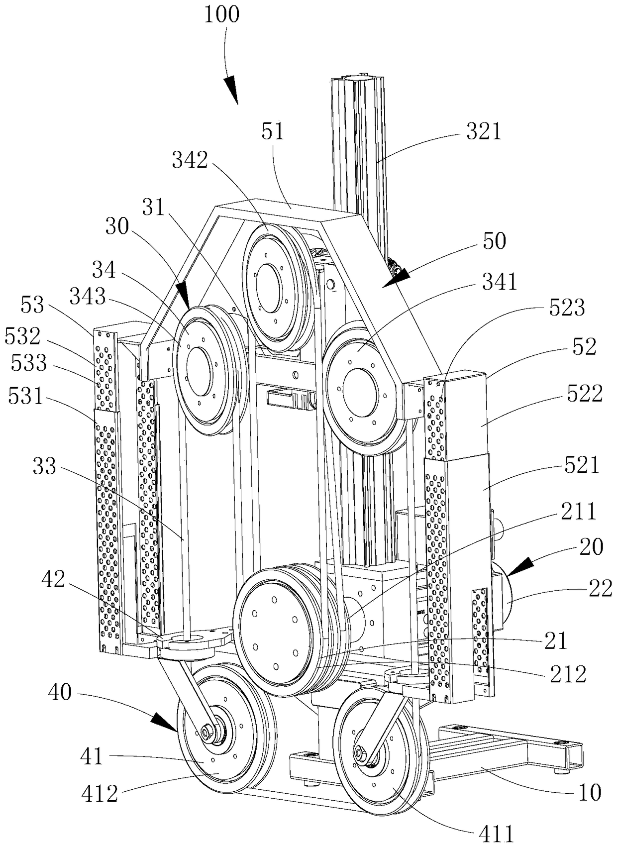
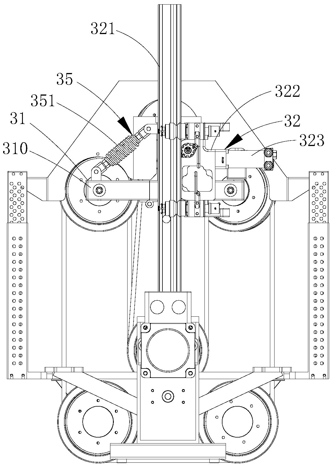
[0037] see Figure 1 to Figure 4 , The first embodiment of the wire saw machine of the present invention will be described below.
[0038] The wire saw machine 100 of this embodiment mainly cuts building concrete, marble blocks, etc.; and the wire saw machine 100 includes a mounting base 10, a driving assembly 20, a walking cutting unloading assembly 30 and a rope receiving assembly 40. Facing the various components of the wire saw machine 100 for further description:
[0039] The driving assembly 20 includes at least one driving wheel 21 and a first driving source 22 for driving the at least one driving wheel 21 to rotate. on, and be connected with at least one driving wheel 21;
[0040] The walking cutting and unloading assembly 30 includes a walking support 31 that can slide up and down above the mounting base 10, a lifting mechanism 32 for making the walking support 31 slide up and down, a diamond beaded rope 33 for cutting objects to be cut, and a diamond beaded rope 33 f...
Embodiment 2
[0072] see Figure 5 and Figure 6 , the implementation of Embodiment 2 is similar to that of Embodiment 1. For details, please refer to the description of Embodiment 1, which will not be described in detail here, and the difference between the two is:
[0073] In Embodiment 1, one end of the tension spring 351a is connected to the first support arm 311, and the other end of the tension spring 351a is connected to the rotating arm 310, and is close to the driven wheel 34 provided on the rotating arm 310, and pulls The centerline of the spring 351a coincides with the centerline of the rotating arm 310 located in the initial area C. As shown in FIG.
[0074] In the second embodiment, the walking frame 31 further includes a second support arm 312a, and the second support arm 312a is vertically arranged on the upper end of the first support arm 311;
[0075] One end of extension spring 351a is connected on the second support arm 312a, and the other end of extension spring 351a i...
Embodiment 3
[0077] see Figure 7 , the implementation of the third embodiment is similar to the implementation of the second embodiment. For details, please refer to the description of the second embodiment, which will not be described in detail here, but the difference between the two is:
[0078] In the second embodiment, the walking frame 31 further includes a second support arm 312a, and the second support arm 312a is vertically arranged on the upper end of the first support arm 311;
[0079] One end of the extension spring 351a is connected to the second support arm 312a, the other end of the extension spring 351a is connected to the rotating arm 310, and is close to the driven wheel 34 provided on the rotating arm 310, and the center line of the extension spring 351a is in line with the rotating arm 310. The central line of the rotating arm 310 when located in the initial region is sandwiched by an angle θ, and 0°<θ<90°.
[0080] In the third embodiment, the walking frame 31 also i...
PUM
 Abstract
Description
Claims
Application Information
 - Generate Ideas
- Intellectual Property
- Life Sciences
- Materials
- Tech Scout
- Unparalleled Data Quality
- Higher Quality Content
- 60% Fewer Hallucinations
Browse by: Latest US Patents, China's latest patents, Technical Efficacy Thesaurus, Application Domain, Technology Topic, Popular Technical Reports.
© 2025 PatSnap. All rights reserved.Legal|Privacy policy|Modern Slavery Act Transparency Statement|Sitemap|About US| Contact US: help@patsnap.com


