Equipment and method for detecting human bodyload impedance of electric stimulation therapy equipment
A technology of load impedance and treatment equipment, applied in the field of human body load impedance detection equipment, can solve problems such as burn skin, high voltage, stinging skin, etc., and achieve the effect of improving the safety of use
- Summary
- Abstract
- Description
- Claims
- Application Information
AI Technical Summary
Problems solved by technology
Method used
Image
Examples
Embodiment 1
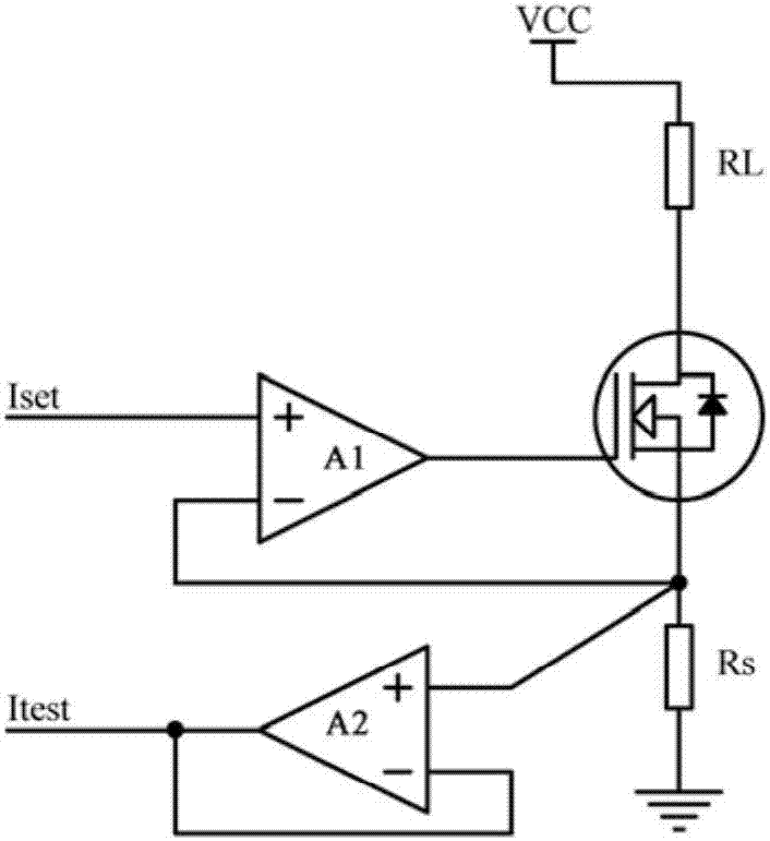
[0048] The stimulation therapy device has a constant current source circuit, which converts the power supply voltage into a constant current; it accepts the control of the current setting voltage, and outputs the expected current to the human body load impedance. This enables current setting. The constant current source circuit itself has a current sampling resistor, and the current flowing through it is the same or proportional to the current flowing through the load impedance of the human body. No additional current sampling resistor is needed, the voltage is directly taken from the current sampling resistor of the constant current source circuit, amplified by the high input impedance amplifier circuit, and the current detection voltage is obtained. This enables current detection.
[0049] In practice, according to whether there is a transformer T in the detection device, the human body load impedance detection device for electrical stimulation therapy equipment is divided ...
Embodiment 2
[0081] According to whether there is a transformer T in the detection device, the human body load impedance detection device for electrical stimulation therapy equipment is divided into two structures.
[0082] Specifically, the detection equipment including the transformer T such as figure 2 as shown,
[0083] Consists of amplifier A1 whose non-inverting input is used to receive the current setting voltage V set , the inverting input of the amplifier A1 is connected to the positive input of the amplifier A2, the inverting input of the amplifier A1 is grounded through the sampling resistor Rs, the output of the amplifier A1 is connected to the base of the NMOS transistor N1; the positive of the amplifier A2 The input terminal is connected to the source stage of the NMOS transistor N1, the inverting input terminal of the amplifier A2 is connected to the output terminal of the amplifier A2, and the output terminal of the amplifier A2 outputs the current detection voltage V te...
PUM
 Abstract
Description
Claims
Application Information
 - R&D Engineer
- R&D Manager
- IP Professional
- Industry Leading Data Capabilities
- Powerful AI technology
- Patent DNA Extraction
Browse by: Latest US Patents, China's latest patents, Technical Efficacy Thesaurus, Application Domain, Technology Topic, Popular Technical Reports.
© 2024 PatSnap. All rights reserved.Legal|Privacy policy|Modern Slavery Act Transparency Statement|Sitemap|About US| Contact US: help@patsnap.com


