Battery pack, power supply device and charging device

A technology of power supply device and charging device, which is applied in the direction of battery circuit devices, circuit devices, battery pack components, etc., can solve problems such as increasing the difficulty and cost of balancing, affecting the use of batteries, and reducing the consistency of internal resistance of batteries, achieving Reduce the failure rate and the difficulty of battery replacement, facilitate maintenance, and avoid energy consumption

Inactive Publication Date: 2017-07-07
丁军浩
View PDF0 Cites 4 Cited by
  • Summary
  • Abstract
  • Description
  • Claims
  • Application Information

AI Technical Summary

Problems solved by technology

Such a battery structure and use method face the following problems: 1. Due to the need for balance during charging, the charging time is too long
2. The circuit of the charging equipment is complicated, the cost is high and the failure rate of the charger is high, and energy is wasted in the balancing process
3. With the gradual aging of the battery during use, the consistency of the internal resistance of the battery cell gradually decreases, the balancing cost is getting higher and higher and the time consumption is gradually increasing, which makes the whole set of batteries fall into a vicious cycle and seriously shortens the battery design service life
4. Due to the series welding package, maintenance is inconvenient, and the detection of a single cell failure will affect the use of the entire battery pack
5. It is easy to produce overshoot phenomenon, and it is easy to explode or spontaneously ignite during the charging process, and there is a high risk
6. The more lithium batteries connected in series, the higher the operating voltage and charging voltage, and the greater the power, which increases the difficulty and cost of balancing. Therefore, many high-power electrical equipment (such as drones) use Two 6S batteries are used in series, which increases the failure rate of the fuselage circuit and also brings inconvenience to the battery replacement work

Method used


Image

  • Battery pack, power supply device and charging device
  • Battery pack, power supply device and charging device
  • Battery pack, power supply device and charging device

Examples


Embodiment Construction

[0023] The present invention will be described in further detail below in conjunction with specific examples, but not as a limitation of the present invention. In the following description, different "one embodiment" or "embodiment" do not necessarily refer to the same embodiment. Furthermore, the particular features, structures, or characteristics of one or more embodiments may be combined in any suitable manner.

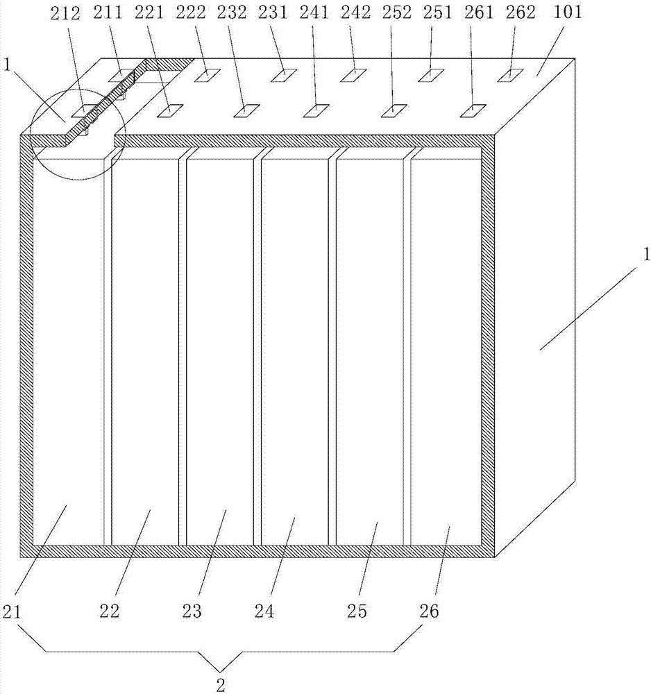
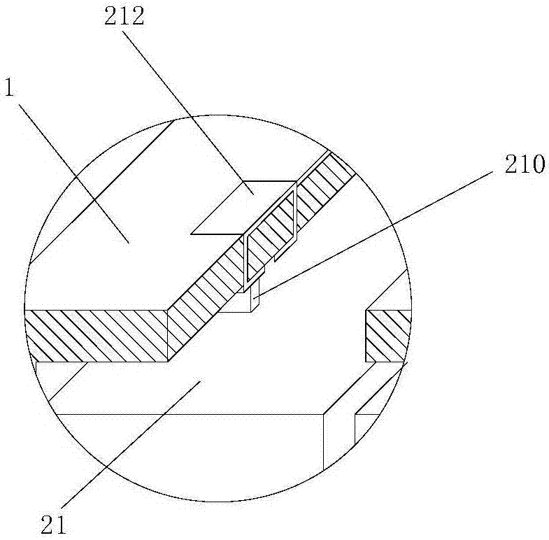
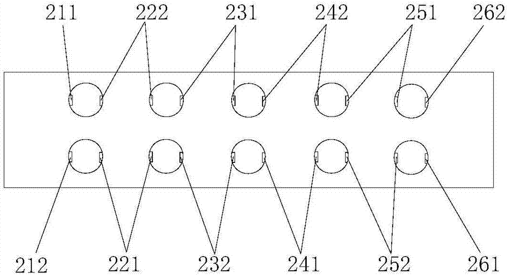
[0024] figure 1 It is a structural schematic diagram of the first embodiment of the battery pack of the present invention. figure 2 for figure 1 Enlarged view of the part in the middle circle. see figure 1 with figure 2 , a battery pack, comprising a casing 1 and a plurality of electric cells 2 arranged in the casing 1, the tabs of the plurality of electric cells 2 are directed in the same direction (such as figure 1 , the tabs are all facing upwards), the first conductive terminals on the shell 1 corresponding to the tabs of the plurality of battery cells ...


PUM


Abstract

The invention discloses a battery pack, a power supply device and a charging device. The battery pack comprises a housing and a plurality of electric cores arranged in the housing; and orientations of tabs of the plurality of electric cores are same. First conductive terminals corresponding to the tabs of the electric cores one by one are arranged at the housing; and each tab is connected with the corresponding first conductive terminal electrically. Besides, the surface with the first conductive terminals of the housing forms a first connecting surface. Therefore, a problem of rapid and secure charging and discharging of the battery can be solved.

Description

technical field [0001] The invention relates to the technical field of lithium batteries, in particular to a battery pack, a power supply device and a charging device. Background technique [0002] Existing battery packs are stacked and packaged with multiple single-chip polymer battery cores with a nominal voltage (such as 3.7 volts), and then packaged in series by welding to obtain a battery pack to supply power to electrical equipment (such as drones, etc.) , Calculate the number of series connection according to the required voltage volts. The common battery is 6 cells connected in series to get a nominal voltage of 22.2 volts. The industry term is called "6S" battery. Due to the charge and discharge characteristics of lithium batteries that cannot be overcharged or overdischarged, it is necessary to lead out a wire from the two electrode contacts of each cell as a "balance line" to detect the voltage value of the single cell during the charging process. After one chip ...

Claims


Application Information

Patent Timeline
Patent Type & Authority Applications(China)
IPC IPC(8): H02J7/00H01M10/058H01M2/26H01M50/531
CPCH01M10/058H02J7/0013H02J7/0045H01M50/531Y02E60/10Y02P70/50
Inventor 丁军浩
Owner 丁军浩
Why Eureka
Try Eureka