Thermal power unit pure-condensing working condition sliding pressure curve determination method with valve throttling loss being taken into consideration
A technology of sliding pressure curve and throttling loss, which is applied in the determination of sliding pressure curve and the determination of sliding pressure curve under pure condensing condition of thermal power units, which can solve the problems of high unit heat loss, cumbersome data process, and inaccurate sliding pressure curve, etc. Achieve the effect of reducing the reduction of economic benefits, simple calculation, and strong timeliness
- Summary
- Abstract
- Description
- Claims
- Application Information
AI Technical Summary
Problems solved by technology
Method used
Image


Examples
specific Embodiment approach 1
[0024] Specific implementation mode one: combine figure 2 Describe this implementation mode, this implementation mode comprises the following steps:
[0025] Step 1: Collect the historical data of all working conditions in the DCS system of the unit;
[0026] Collect the opening of each valve group, comprehensive valve position command, unit main steam pressure, unit main steam temperature, first extraction point pressure, first extraction point temperature, main steam flow and unit load;
[0027] Step 2: Screen the data in step 1, and group and count the data in the load interval to be collected;
[0028] Select 50% unit rated load ± 1MW, 60% unit rated load ± 1MW, 70% unit rated load ± 1MW and 80% unit rated load ± 1MW and the main steam temperature is the rated main steam temperature ± 1 ℃ interval data for classification ;
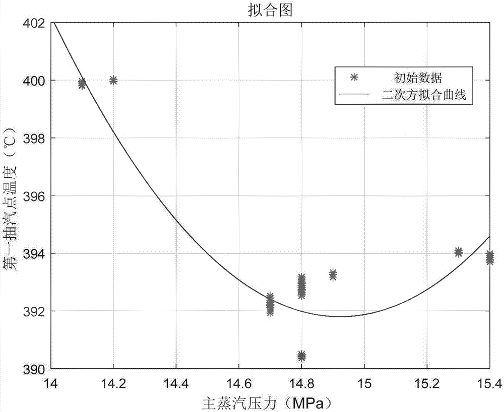
[0029] Step 3: Use the data analysis of each load interval to obtain the optimal main steam pressure corresponding to the corresponding load point...
specific Embodiment approach 2
[0032] Specific implementation mode two: combination figure 2 To illustrate this embodiment, the historical data collected in step 1 of this embodiment needs to be the operating status data of the sequence valve of the unit, and the data includes all loads between the minimum output value and the rated value of the unit load. The reason for this setting is that the sliding pressure curve is designed for the operating condition of the sequence valve of the unit, and the purpose of collecting full working condition data is to obtain a more accurate optimal pressure point in the least square method fitting in step 3 The purpose of collecting the opening degree of each valve group and the comprehensive valve position command is to verify whether the unit is in the operating state of the sequence valve and to obtain the law of the sequence valve, to collect the main steam pressure of the unit, the temperature of the main steam of the unit, the pressure of the first extraction The ...
specific Embodiment approach 3
[0033] Specific implementation mode three: combination figure 2 Describe this embodiment, the step of drawing the sliding pressure curve in step 4 of this embodiment: calculate the sliding pressure curve of the sliding pressure section according to the optimal main steam pressure at each load point obtained in step 3, and the calculation method is based on the minimum The polynomial function linear fitting of the square method is combined with the minimum main steam pressure of the boiler steady combustion and the rated main steam pressure of the unit to obtain the final sliding pressure curve. Other compositions and connections are the same as those in Embodiment 1 or Embodiment 2.
[0034] Since the main steam pressure of the middle and low pressure constant pressure section of the constant-sliding-constant sliding pressure method is the lowest pressure of the boiler for stable combustion, and the high pressure constant pressure section is the rated main steam pressure of t...
PUM
 Abstract
Description
Claims
Application Information
 - R&D
- Intellectual Property
- Life Sciences
- Materials
- Tech Scout
- Unparalleled Data Quality
- Higher Quality Content
- 60% Fewer Hallucinations
Browse by: Latest US Patents, China's latest patents, Technical Efficacy Thesaurus, Application Domain, Technology Topic, Popular Technical Reports.
© 2025 PatSnap. All rights reserved.Legal|Privacy policy|Modern Slavery Act Transparency Statement|Sitemap|About US| Contact US: help@patsnap.com