
Half-rate clock data recovery circuit

A clock data recovery and half-rate technology, which is applied to logic circuits with logic functions, electrical components, digital transmission systems, etc., can solve the problem that the sampling position deviates from the optimal sampling point, the eye diagram of the input signal is not an ideal symmetrical shape, and the data Increased error rate and other issues

Active Publication Date: 2017-07-04
REALTEK SEMICON CORP
View PDF6 Cites 4 Cited by
  • Summary
  • Abstract
  • Description
  • Claims
  • Application Information

AI Technical Summary

Problems solved by technology

[0003] However, in the actual application environment, due to the attenuation of the transmission medium, the eye diagram of the input signal is often not an ideal symmetrical shape, and the edge sampling circuit often has a certain data hold time (hold time)
In this case, using an in-phase clock signal and a quadrature-phase clock signal with a fixed phase difference of 90 degrees for sampling will cause the sampling position of the input signal to deviate from the optimal sampling point in the eye diagram when the loop is locked, resulting in data errors rate increase

Method used


Image

  • Half-rate clock data recovery circuit
  • Half-rate clock data recovery circuit
  • Half-rate clock data recovery circuit

Examples


Embodiment Construction

[0011] Embodiments of the present invention will be described below in conjunction with related figures. In the drawings, the same reference numerals indicate the same or similar components or method flows.

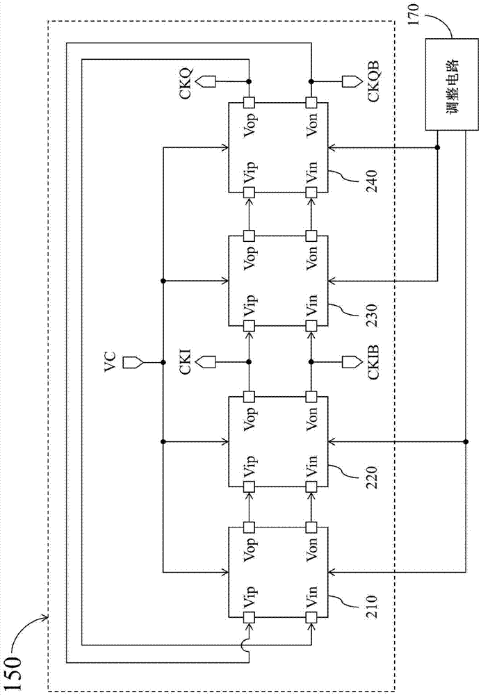
[0012] figure 1 It is a simplified functional block diagram of a half-rate clock data recovery circuit (half-rate clock data recovery circuit) 100 according to an embodiment of the present invention. The half rate clock data recovery circuit 100 is used to provide a clock data signal (clock data signal) DOUT to a data processing circuit (data processing circuit) 102 . like figure 1 As shown, the half rate clock data recovery circuit 100 includes a control voltage generation circuit 110, a data sampling circuit 120, an edge sampling circuit 130, a phase detection circuit 140, a voltage controlled oscillator 150, a frequency detection circuit 160, a The adjustment circuit 170 , a control circuit 180 , and a storage device 190 .

[0013] In the half rate clock data recov...


PUM


Abstract

The invention provides a half-rate clock data recovery circuit. The half-rate clock data recovery circuit comprises a voltage-controlled oscillator set to produce a data sampling clock and an edge sampling clock according to a control voltage; an adjusting circuit set to dynamically control the voltage-controlled oscillator to adjust a phase difference between the data sampling clock and the edge sampling clock to be different from 90 DEG in multiple testing periods; and a control circuit set to indicate the adjusting circuit to control the voltage-controlled oscillator in multiple testing periods by respectively utilizing different control value combinations, and record multiple recovery signal quality pointers respectively corresponding to multiple testing periods; and then the control circuit can indicate the adjusting circuit to control the voltage-controlled oscillator by use of a control value combination corresponding to an optimal quality pointer in the multiple recovery quality pointers.

Description

technical field [0001] The present invention relates to a half-rate clock data recovery circuit, in particular to a half-rate clock data recovery circuit that can dynamically change the delay of sampling signals. Background technique [0002] A traditional half-rate clock data recovery circuit uses a voltage-controlled oscillator to generate an in-phase clock signal and a quadrature-phase clock signal with a phase difference of 90 degrees. In the traditional half-rate clock data recovery circuit, the data sampling circuit will use the aforementioned in-phase clock signal as the data sampling clock of the input signal, while the edge sampling circuit will use the aforementioned quadrature phase clock signal as the edge sampling clock of the input signal . When the edge of the quadrature-phase clock signal is aligned with the edge of the eye diagram of the input signal, the edge of the in-phase clock signal should theoretically be aligned with the center of the eye diagram of...

Claims


Application Information

Patent Timeline
Patent Type & Authority Applications(China)
IPC IPC(8): H03K19/20
CPCH03K19/20H04L1/24H04L7/0079H04L7/033H03L7/087H03L7/091H03L7/0995H03L7/113H03L2207/06H03L7/0807H03L7/093
Inventor 刘剑
Owner REALTEK SEMICON CORP
Learn More