
Sectionalized biomass combustion device

A staged combustion and biomass technology, applied in the direction of combustion equipment, solid fuel combustion, lighting and heating equipment, etc., can solve the problems of overall combustion obstacles, easy slagging and agglomeration, low thermal efficiency, etc., to reduce combustion losses , Improve adaptability and improve thermal efficiency

Pending Publication Date: 2017-07-04
XIAN SENWAS AGRI SCI & TECH
View PDF5 Cites 8 Cited by
  • Summary
  • Abstract
  • Description
  • Claims
  • Application Information

AI Technical Summary

Problems solved by technology

There are various deficiencies in existing biomass combustion devices using the above combustion technologies. One, the fuel cannot be fully burned, and there is always a loss of 5%-10% incomplete combustion; two, biomass particles mostly use woody raw materials, The impurity content in the raw material is slightly high, or when other biomass fuels are used, it is easy to slagging and agglomerating, causing overall combustion obstacles; 3. The temperature adjustment range is small, which is not suitable for industries with large temperature difference adjustment, especially when lower temperatures are required; 4. Unreasonable combustion chamber structure and air distribution design lead to low thermal efficiency and high operating costs; 5. High overall design and manufacturing costs cause difficulties in professional application and promotion

Method used


Image

  • Sectionalized biomass combustion device
  • Sectionalized biomass combustion device
  • Sectionalized biomass combustion device

Examples


Embodiment Construction

[0027] The present invention will be described in detail below in conjunction with the accompanying drawings and specific embodiments.

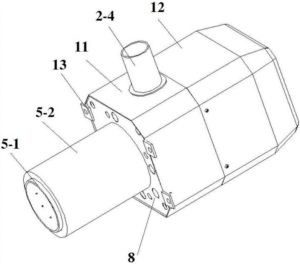
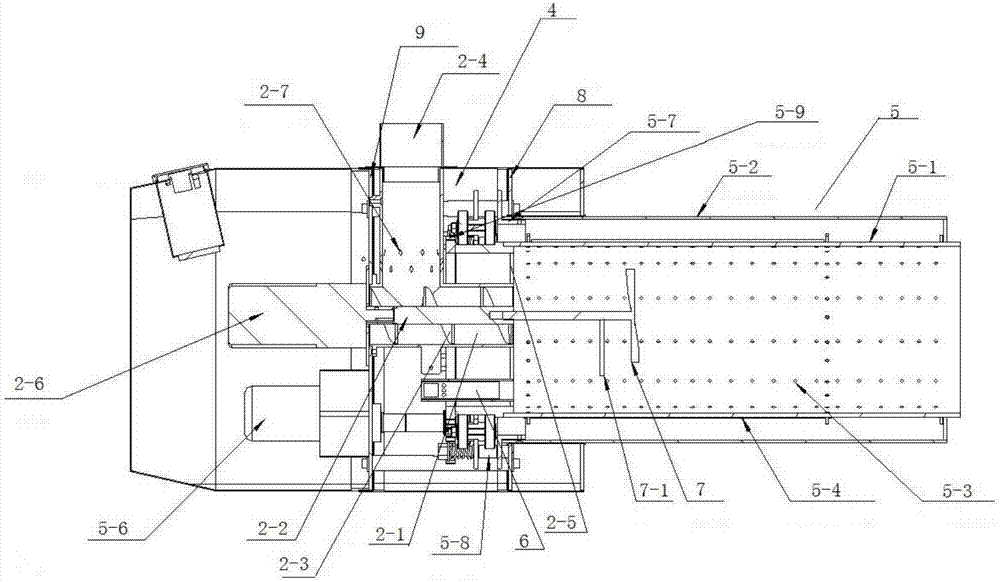
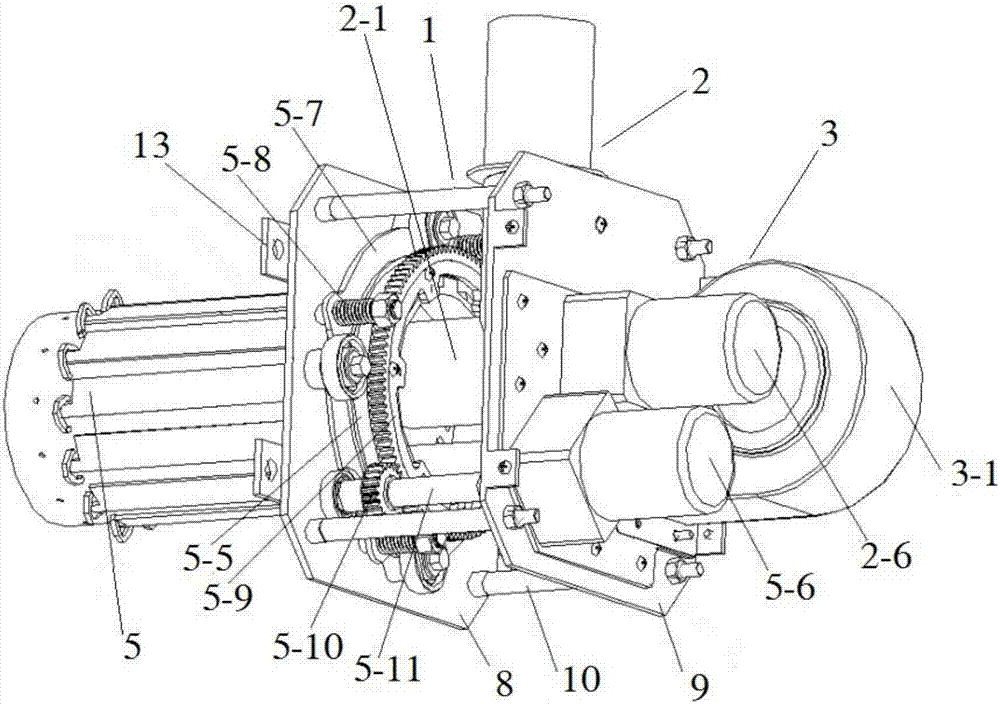
[0028] The overall schematic diagram, front sectional view and structural schematic diagram of a biomass staged combustion device of the present invention, such as figure 1 , 2 As shown in and 3, the embodiment of the present invention provides a biomass staged combustion device, including a frame 1, the frame 1 includes a first mounting plate 8 and a second mounting plate 9, the first mounting plate 8 and the second mounting plate The plates 9 are connected by several locking rods 10, and a bellows cover 11 is arranged along the circumferential direction of the first mounting plate 8 and the second mounting plate 9, and a phoenix chamber 4 is formed between the first mounting plate 8 and the second mounting plate 9, and the machine The frame 1 is provided with a feeding device 2, an air supply device 3, a combustion chamber 5 and an igniter...


PUM


Abstract

The invention provides a sectionalized biomass combustion device. The sectionalized biomass combustion device comprises a rack. A feeding device, an air supply device, a combustion chamber and an igniter are arranged on the rack. The feeding device communicates with the combustion chamber. An ignition port is formed in the combustion chamber. The air supply device is used for blowing air into an air chamber. The air chamber communicates with the feeding device and the combustion chamber. A flow disturbing plate is arranged in the combustion chamber. The sectionalized biomass combustion device has the beneficial effects that flow disturbing plates with different sizes can be adopted to change the primary tangent air direction according to the power of a combustion machine and the diameter of a combustion cylinder, so that slight reversal combustion is formed, sectionalized combustion is formed by properly increasing the combustion temperature of the rear section of the combustion cylinder, the rear section is a thermal decomposition section, and the front section is a high-temperature gasification section; and by widening the combustion temperature adjustment range, high-temperature biomass raw materials can be combusted and decomposed, and the adaptability of the device is improved, so that fuel is combusted sufficiently, the loss caused by insufficient combustion is reduced, and the heat efficiency is greatly improved.

Description

technical field [0001] The invention belongs to the technical field of biomass burning equipment, and relates to a staged biomass burning device. Background technique [0002] Biomass fuel refers to the burning of biomass materials as fuel, generally mainly agricultural and forestry wastes, such as straw, sawdust, bagasse, rice bran, etc., which are mainly different from fossil fuels. According to the current national policy and environmental protection standards, direct combustion of biomass fuel is a highly polluting fuel, which is only used in large stoves in rural areas and is not allowed to be used in cities. The application of biomass fuel is mainly biomass briquette fuel, that is, agricultural and forestry wastes are used as raw materials, and through crushing, mixing, extrusion, drying and other processes, they are made into various shapes such as granules, which can be directly burned as a clean fuel. . Biofuels shaped like pellets are biomass pellet fuels. As a n...

Claims


Application Information

Patent Timeline
IPC IPC(8): F23B90/06
CPCF23B90/06
Inventor 肖吉林党晓辉卢俊王睿温华中徐彬付文哲王波王曼
Owner XIAN SENWAS AGRI SCI & TECH
Learn More