
Semiconductor element and manufacturing method thereof

A manufacturing method and semiconductor technology, applied in semiconductor devices, semiconductor/solid-state device manufacturing, electrical components, etc., can solve problems affecting the integrity of spacers and complicated manufacturing process steps

Active Publication Date: 2019-10-11
POWERCHIP SEMICON MFG CORP
View PDF4 Cites 0 Cited by
  • Summary
  • Abstract
  • Description
  • Claims
  • Application Information

AI Technical Summary

Problems solved by technology

[0003] However, the disadvantage of the above-mentioned prior art is that additional deposition of a stress layer (usually a silicon nitride layer) and a stress layer removal step after the SMT annealing process are required, so the manufacturing process steps are more complicated
In addition, when the stress layer is removed by hot phosphoric acid solution, it is easy to affect the integrity of the spacer of the gate structure

Method used


Image

  • Semiconductor element and manufacturing method thereof
  • Semiconductor element and manufacturing method thereof
  • Semiconductor element and manufacturing method thereof

Examples


Embodiment Construction

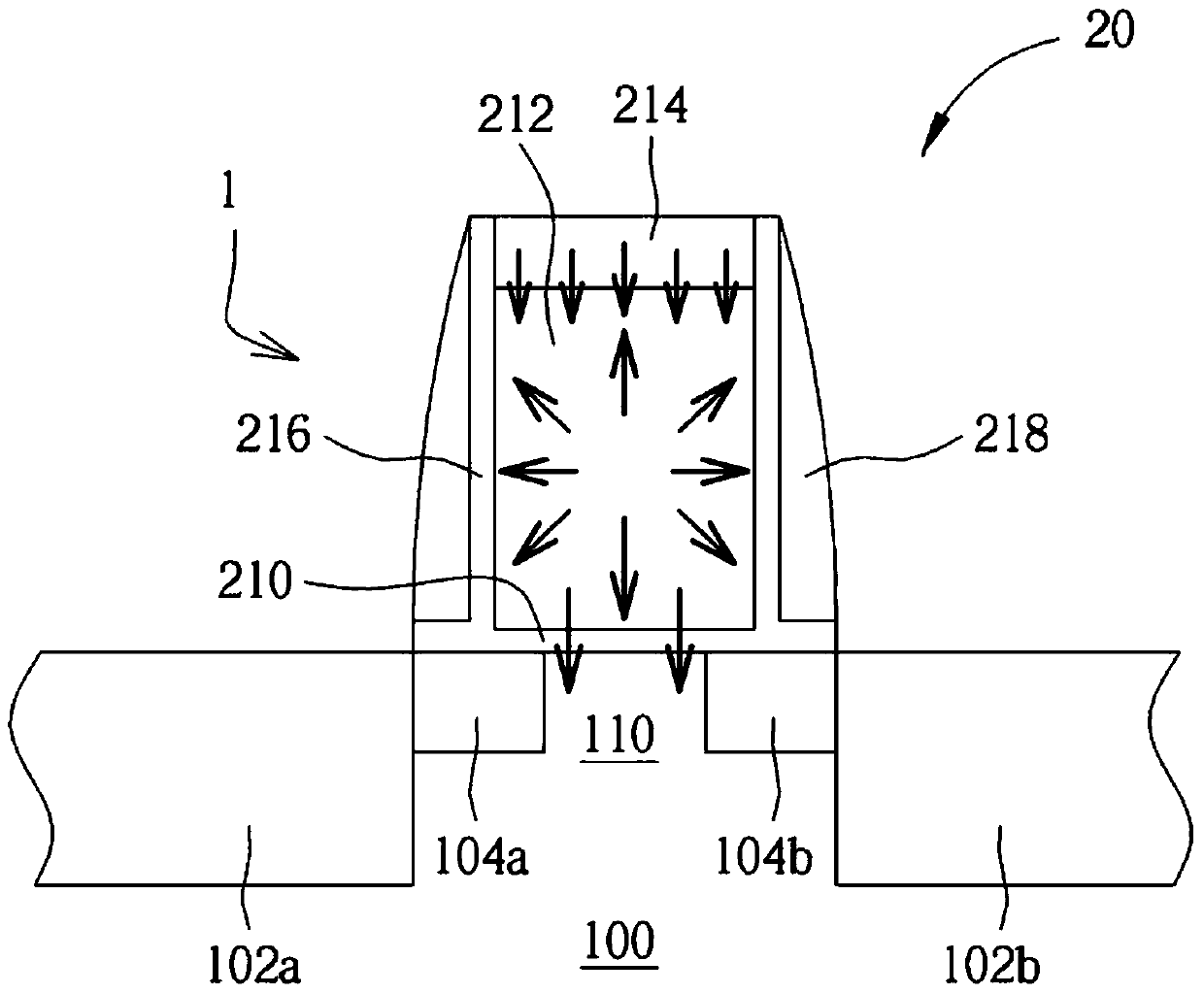
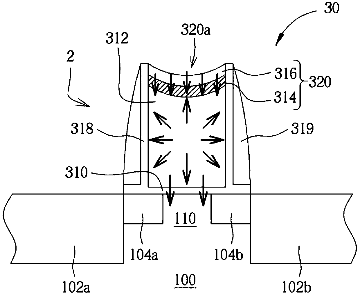
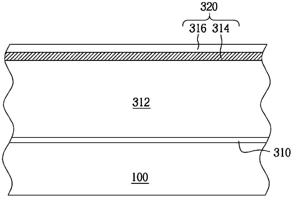
[0042] Although the present invention is disclosed as follows with the embodiment, it is not intended to limit the present invention. Anyone familiar with this technology can make some changes and modifications without departing from the spirit and scope of the present invention. Therefore, the protection of the present invention The scope should be defined by the appended claims, and in order to simplify the description, the details of some existing structures and manufacturing process steps will not be disclosed here.

[0043] Likewise, the figures shown are schematic diagrams of devices in the embodiments but are not intended to limit the size of the devices. In particular, in order to make the present invention more clearly presented, the sizes of some components may be enlarged in the figures. Furthermore, the same components disclosed in multiple embodiments will be marked with the same or similar symbols to make the description easier and clearer.

[0044] see figure 1...


PUM


Abstract

The invention discloses a semiconductor element and a manufacturing method thereof. The semiconductor element includes a substrate; a source doping region disposed in the substrate; a drain doping region disposed in the base and connected with the source doping region separated by a predetermined distance; a channel region between the source doping region and the drain doping region; and a gate structure disposed on the channel region, wherein the gate structure includes a gate dielectric layer, a a gate conductive layer, and a composite stress guiding layer.

Description

technical field [0001] The invention relates to a semiconductor element and its manufacturing method, in particular to an improved metal oxide semiconductor (MOS) transistor structure and its manufacturing method. Background technique [0002] It is known that the stress memorization technique (SMT) has been applied in the semiconductor manufacturing process to improve the electrical performance of the N-type metal oxide semiconductor (NMOS) device. The method includes covering a gate structure with The tensile stress layer is subjected to an SMT annealing process to recrystallize the gate conductive layer, and then the stress layer is removed. After the stress layer is removed, the stress effect can continue to affect the component. The stress effect can enhance the mobility of charges through the channel, which is used to improve device performance. [0003] However, the disadvantage of the above-mentioned prior art is that additional deposition of a stress layer (usuall...

Claims


Application Information

Patent Timeline
Patent Type & Authority Patents(China)
IPC IPC(8): H01L29/423H01L21/336H01L29/786
CPCH01L29/423H01L29/66742H01L29/7869
Inventor 戴炘林玮翔吕明政
Owner POWERCHIP SEMICON MFG CORP
Learn More