Adaptive blade tip processing table fixture for aero-engine fan blade machining

A technology for aero-engine and fan blades, which is applied to manufacturing tools, workpiece clamping devices, metal processing equipment, etc., can solve problems such as poor practicability, and achieve good practicability and prevent loosening.

Active Publication Date: 2018-09-04
NORTHWESTERN POLYTECHNICAL UNIV
View PDF6 Cites 0 Cited by
  • Summary
  • Abstract
  • Description
  • Claims
  • Application Information

AI Technical Summary

Problems solved by technology

[0006] In order to overcome the disadvantages of poor practicability of the existing fixtures, the present invention provides an adaptive blade tip process fixture applied to the machining of aeroengine fan blades

Method used


Image

  • Adaptive blade tip processing table fixture for aero-engine fan blade machining
  • Adaptive blade tip processing table fixture for aero-engine fan blade machining
  • Adaptive blade tip processing table fixture for aero-engine fan blade machining

Examples


Embodiment Construction

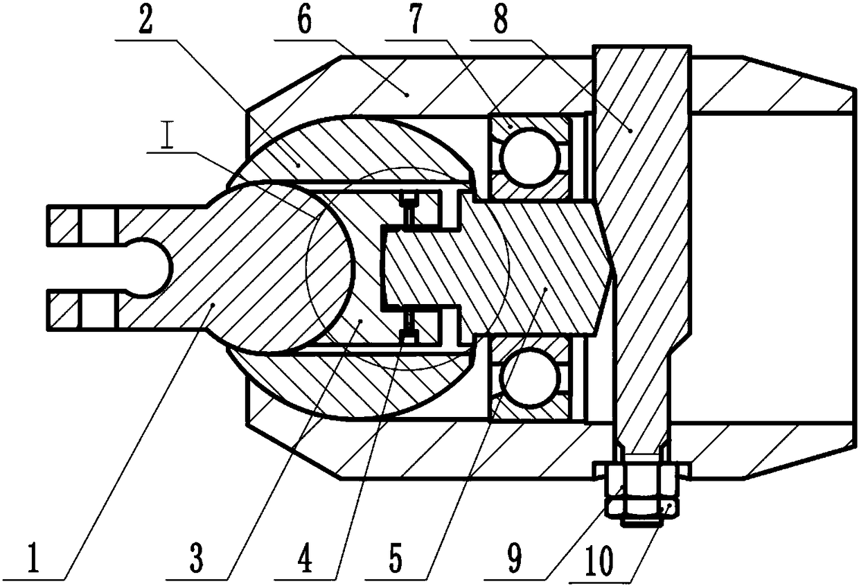
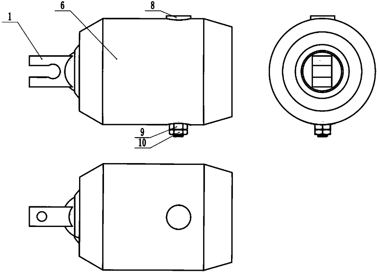
[0017] The following examples refer to Figure 1~4 .

[0018] The self-adaptive blade tip process fixture used in the processing of aeroengine fan blades in the present invention includes a chuck 1, a rolling body 2, a friction block 3, a screw 4, a push rod 5, a casing 6, a bearing 7, a push rod 8, and a hex nut 9 and snap nut 10.

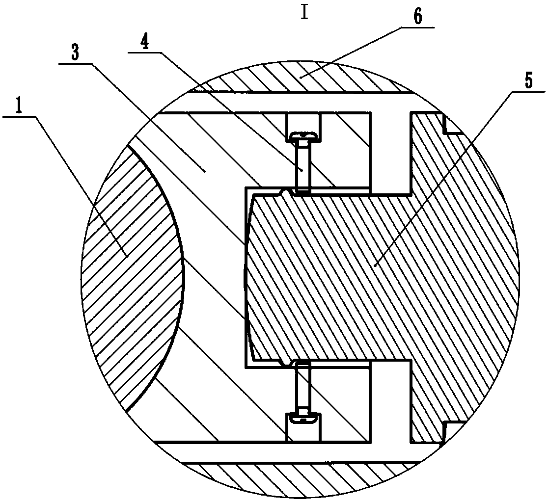
[0019] The front end of the chuck 1 is provided with a bolt hole, and adopts a rigidity-weakened elastic design, and the rear part is designed as a sphere. The center line of the bolt hole is perpendicular to the center plane of the fixture, and the center of the spherical surface of the tail is located on the center plane of the fixture.

[0020] The outside of the rolling body 2 is designed as a sphere, the inner front end is designed as a spherical surface, and is matched with the rear spherical surface of the chuck 1, and the inner rear end is designed as a cylindrical surface.

[0021] The front end of the friction block 3 is designed as a...


PUM


Abstract

The invention discloses a self-adaptive blade tip process table clamp applied to aero-engine fan blade machining. The self-adaptive blade tip process table clamp is used for solving the technical problem of poor practicality of an existing clamp. According to the technical scheme, the self-adaptive blade tip process table clamp comprises a chuck, a rolling body, a friction block, a screw, an ejector rod, a bearing, a push rod, an outer shell, a hexagonal nut and a binding nut. Elastic design is adopted at the front end of the chuck, sphere design is adopted at the tail of the chuck, and the chuck can freely rotate in the rolling body. The rolling body can rotate in the outer shell, the movable range of the chuck is further widened, it is guaranteed that the chuck can adapt to the position of a blade tip process table well, and self-adaptive clamping of the clamp is achieved. In a fast clamping mechanism, by means of vertical movement of the push rod, the ejector rod is driven to horizontally move in the bearing, and therefore the friction block and the chuck are fast jacked. The push rod is fixed through the hexagonal nut and the binding nut and prevented from loosening. The clamp can carry out locating and clamping by adapting to the position of a blade tip by adjusting the position of the chuck, metal contaminating a titanium alloy is not introduced, and good practicality is achieved.

Description

technical field [0001] The invention relates to a fixture, in particular to a self-adaptive blade tip process bench fixture used in the processing of aeroengine fan blades. Background technique [0002] The fan blade is one of the core components of the aero-engine, and its curved surface shape and manufacturing precision directly affect the propulsion efficiency of the aero-engine. The technological characteristics of aero-engine blades are: the blade has a thin-walled structure, has a complex free-form surface, the structure has the characteristics of bending, twisting, and sweeping, and has high precision requirements. These characteristics put forward quite high requirements for the clamping of the blade before processing. [0003] During processing, it is necessary to rely on the fixture to ensure that the blade is in the correct position and clamping, and to prevent the position change and workpiece deformation caused by the loosening of the fixture due to cutting forc...

Claims


Application Information

Patent Timeline
Patent Type & Authority Patents(China)
IPC IPC(8): B25B11/00B23Q3/00B22D19/04
CPCB22D19/04B23Q3/00B25B11/00
Inventor 郭龙钊刘维伟胡媛王增强孙成陆
Owner NORTHWESTERN POLYTECHNICAL UNIV
Why Eureka
Try Eureka