Hydraulic driven angle head

An angle head and hydraulic technology, applied in the direction of drive devices, metal processing machinery parts, metal processing equipment, etc., can solve the problems of temperature rise, gear transmission rate and torque force effect, etc., to achieve high cutting speed, strong cutting torque, Ease of use

Pending Publication Date: 2017-06-27
上海司恩金属加工技术有限公司
View PDF8 Cites 2 Cited by
  • Summary
  • Abstract
  • Description
  • Claims
  • Application Information

AI Technical Summary

Problems solved by technology

[0004] The purpose of the present invention is to provide a hydraulically driven angle head, which has the advantages of high-pressure hydraulic drive, and solves the problem that most of the existing drive angle heads are driven by motors, and the torque force effect of the gear transmission rate is poor, and they are easily affected by temperature rise.

Method used


Image

  • Hydraulic driven angle head

Examples


Embodiment Construction

[0015] The following will clearly and completely describe the technical solutions in the embodiments of the present invention with reference to the accompanying drawings in the embodiments of the present invention. Obviously, the described embodiments are only some, not all, embodiments of the present invention. Based on the embodiments of the present invention, all other embodiments obtained by persons of ordinary skill in the art without making creative efforts belong to the protection scope of the present invention.

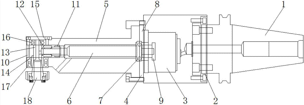
[0016] see figure 1 , the hydraulic drive angle head, including the installation handle 1, the left side of the installation handle 1 is fixedly connected with the ball volume motor 3 through the first connecting flange ring 2, and the left side of the ball volume motor 3 is fixedly connected through the second connecting flange ring 4 Angled head housing 5, the right side of the mounting handle 1 is provided with a water inlet, the left side of the bottom of ...


PUM


Abstract

The invention discloses a hydraulic driven angle head. The hydraulic driven angle head comprises a mounting handle, wherein a ball positive displacement motor is fixedly connected with the left side of the mounting handle through a first connecting flange ring; an angle head casing is fixedly connected with the left side of the ball positive displacement motor through a second connecting flange ring; a transmission shaft is arranged in the angle head casing; a ball bearing is fixedly connected with the right side of the transmission shaft; a fixed-core flange ring matched with the ball bearing for use is fixedly connected with the left side of the ball positive displacement motor. The hydraulic driven angle head is not required to be driven to rotate by a machine tool spindle motor and is mainly driven to perform rotary cutting by high hydraulic pressure, so that the cutting torque is higher, the cutting rotating speed is higher, key slots, cross holes, inclined planes and cambered surfaces of parts required to be machined in deeper, smaller and narrower space can be machined, water is introduced into the angle head for cooling, and the service time is not influenced by temperature rise. Cooling and lubricating effects of a cutting tool and a workpiece are better and precision and smooth finish of a cutting surface are better.

Description

technical field [0001] The invention relates to the technical field of numerical control machine tools, in particular to a hydraulic drive angle head. Background technique [0002] Machining has been pursuing high-precision and high-efficiency processing technology. Although high-end CNC machine tools have been able to solve the processing problems of most complex parts, special and complex parts cannot be completely solved by CNC machine tools alone. Some precision machine tools must be used to expand the machining capabilities of machine tools. For example, the hydraulically driven angle head, which can use high-pressure water pressure to drive the cutting tool to rotate to process workpieces at various angles on the side, especially for parts that require side processing in narrow spaces, has a very good ability to solve. [0003] The angle head is an important functional accessory on the CNC machine tool. Most of the existing angle heads are driven by the mechanical pow...

Claims


Application Information

Patent Timeline
Patent Type & Authority Applications(China)
IPC IPC(8): B23Q5/06
CPCB23Q5/06
Inventor 肖阳紫
Owner 上海司恩金属加工技术有限公司
Why Eureka
Try Eureka