
Waste rock and cementing layered wedge bonding filling mining technology and structure thereof

A backfill mining and cemented backfill technology, which is applied in the fields of backfill, ground mining, mining equipment, etc., can solve the problems of low labor productivity, ore block production capacity, unreasonable application of waste rock, troublesome surface storage, etc., so as to reduce the surface Storage and transportation costs, improving the utilization rate of waste rock, and the effect of low cost

Active Publication Date: 2017-06-20
GUANGXI GAOFENG MINE IND
View PDF11 Cites 23 Cited by
  • Summary
  • Abstract
  • Description
  • Claims
  • Application Information

AI Technical Summary

Problems solved by technology

[0007] The invention provides a mining process and structure that can use a large amount of underground waste rocks for backfilling, combined with the waste rock and cemented layered wedge filling of full tailings cemented layered wedged filling, and solves the complex process and high cost of the prior art , labor productivity and ore block production capacity are relatively low, waste rock cannot be used reasonably, surface storage is troublesome, and transportation costs are high

Method used


Image

  • Waste rock and cementing layered wedge bonding filling mining technology and structure thereof
  • Waste rock and cementing layered wedge bonding filling mining technology and structure thereof
  • Waste rock and cementing layered wedge bonding filling mining technology and structure thereof

Examples


Embodiment Construction

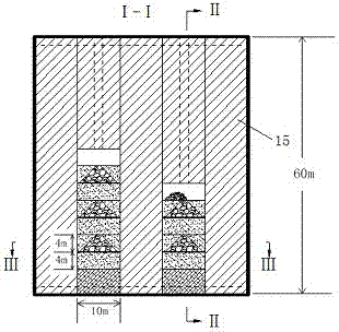
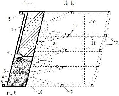
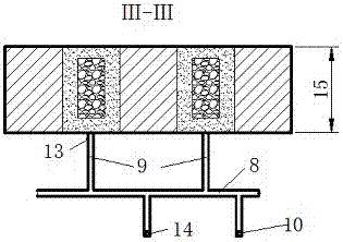
[0025] The specific use case of the mining scheme proposed by the present invention is: for the mining of the above-mentioned types of ore bodies, the stage height is 40-60m, and the length of the ore block is generally 50-60m, which can be reduced to 30-60m when the ore body is broken and the ground pressure is large. 40m. First pass through the middle section of the ore body floor and the ramp to excavate the mining area contact road, subsection entry, subsection exit entry, and slip shaft, and then excavate the return air filling shaft close to the ore body floor to communicate with the upper and middle section of the prospecting entry . Before mining, excavate the cutting horizontal roadway at the bottom of the ore block, excavate the cutting roadway along the ore body, and use the cutting horizontal roadway as the free surface to pull the bottom along the cutting roadway. The plastic bellows of the holes are connected to the small well for filling and drainage, and the r...


PUM


Abstract

The invention discloses a waste rock and cementing layered wedge bonding filling mining technology and a structure thereof. In the mining process through an upward horizontal cut and fill method, upward stoping and filling are conducted by adoption of layers with the depth being 3-4 m; three layers serve as a section; the first layer and the third layer are separately subjected to cementing filling through tailings; the second layer in the middle is filled with waste rock in a spaced and mixed mode; the bottom face pavement range is set according to the size of a stope, and a certain distance is kept from the periphery; and the periphery of a waste rock pile is still subjected to cementing filling through tailings, and the tailings are in contact and connection with cementing filling bodies of the upper layer and the lower layer. By adoption of the waste rock and cementing layered wedge bonding filling mining technology and the structure thereof, the problems that in the prior art, technologies are complex, the cost is high, the labor productivity and the ore block production capacity are relatively low, and waste rock cannot be reasonably applied are solved, and by adoption of a layered wedge bonding mixed filling method, the strength of the filling bodies is ensured, a large amount of downhole waste rock is consumed, cementing filling materials are saved, and the layered wedge bonding mixed filling method has the characteristics of being safe in operation, high in filling efficiency and low in cost.

Description

technical field [0001] The invention relates to an upward horizontal layered filling mining structure and its technology in an underground mine, in particular to a waste rock and cemented layered wedging filling mining technology and its structure. Background technique [0002] When the surface does not allow caving, the ore grade is high, the value of the ore deposit is high, or the surrounding rock of the upper and lower walls of the ore body is moderately stable or poorly stable, the filling mining method is generally used for mining. In this method, the filling body is used to control surrounding rock collapse and surface movement for ground pressure management, and mining is carried out on or under the protection of the formed filling body. It has strong adaptability, high ore recovery rate, low dilution rate, safer operation, can utilize industrial waste, protect the surface, etc.; the disadvantage is that the process is complicated, the cost is high, and the labor pro...

Claims


Application Information

Patent Timeline
IPC IPC(8): E21C41/16E21F15/00
Inventor 罗先伟赵元元韦军
Owner GUANGXI GAOFENG MINE IND
Learn More