
Modular patient support system for use in radiotherapy treatments

a patient support system and module technology, applied in the field of module patient support system for use in radiotherapy treatments, can solve the problem of limited positioning rang

Active Publication Date: 2006-07-18
SINMED
View PDF13 Cites 43 Cited by
  • Summary
  • Abstract
  • Description
  • Claims
  • Application Information

AI Technical Summary

Benefits of technology

[0005]Apart from the advantage of a completely radiotransparent support, the modular system according to the invention has the further advantages that with the radiotransparent supporting portion, the modular portion can be made smaller than is usual with said known patient supports. With the known structures, the metal reinforcements must be kept outside the range to be irradiated, therefore outside of the body contour of the patients to be treated. The advantages of a less wide support are, among other things, that the irradiating member can be brought closer to the tumors to be treated and that the entity of fixed basic portion and modular portion can be positioned within a larger range in relation to said radiating member. With the known supports, the positioning range is limited because of the dimensions of said entity. Therefore, the radiating member will easily abut the support or the support will easily abut the stationary parts of the irradiation device.
[0006]A further advantage is that the specific modular portions can be made for irradiating tumors in specific target areas, to which end the modular portions can be adapted in shape. The modular patient support can be made narrower than usual, as a result of which more adjusting possibilities are provided. This also enables a more effective irradiation and conservation of a greater amount of healthy tissue. Since the modular portions are intended for a certain target area, they can be provided with speciale fixing positions for accessories to be used.
[0007]Preceding the actual irradiation, the patient mostly passes through the CT scanning device, where the tumor(s) is / will be located. Using this information, an irradiation planning is made. A great advantage is achieved by providing the CT scanner with a patient support which corresponds to the patient support according to the invention as far as positioning of the patient, dosimetric properties and markers are concerned. The previously required calculating operations of the CT support to the form and dosimetric properties of the patient support in the irradiating device can be omitted. This makes planning the irradiation much quicker, more effective and reliable and positioning of the patient is much more accurate and better reproducible. This again leads to a more accurate and more effective irradiation of the tumor.
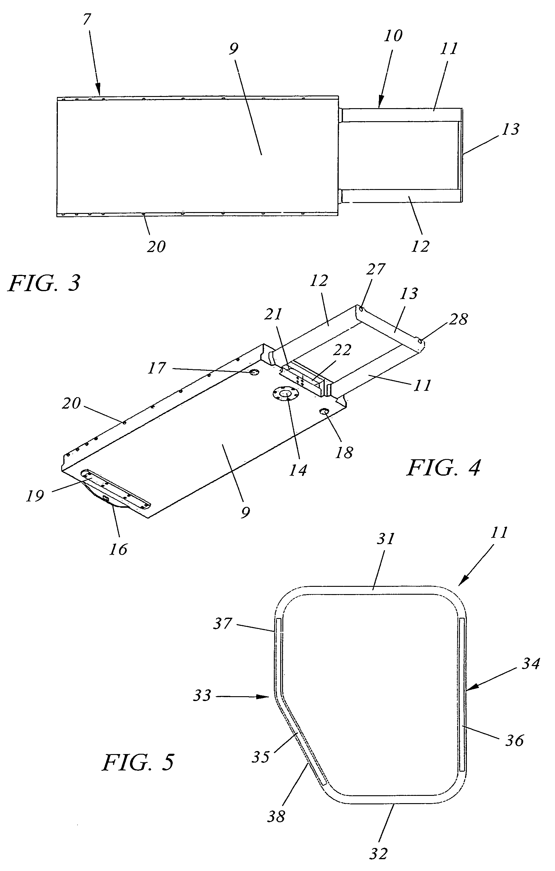
[0009]The dosimetric properties are especially important at the sides, since they cover a much larger rotational angle of the irradiation member than the bottom and top sides of the tubular sleeves per se do. The dosimetric properties directly depend on the specific density and the properties of the material passed by the radiation. By the specific construction of the profiles it is achieved that the beam of radiation is weakened as little as possible and an effect of accumulation of radiation on the skin is minimized, while the strength and stiffness of said profiles remains guaranteed.
[0010]According to a yet further development, it is provided that the tubular sleeves, seen in cross-section, become narrower from the upwardly situated plane of contact with a modular part downwards. A preferred embodiment provides for, that the tubular sleeves have an obliquely extending plane at the outwardly facing sides. Thus, the stiffness and strength of the supporting arms can remain guaranteed, while a larger degree of free movement of the radiation member enhances its number of adjusting possibilities.
[0013]In order to establish an accurate positioning which will be exactly reproduced again on renewed placement of a modular portion, it is necessary to mount positioning means in the radiotransparent portion of the support as well. According to a further development, to that end, second positioning means are provided, comprising one or more pins mounted on a modular portion, said pins being made of a radiotransparent material, and corresponding holes for receiving the pins in the radiotransparent supporting portion of the fixed basic portion. These second positioning means prevent the modular portion from moving in the remaining level of freedom, therefore in vertical direction, and also serve for transmit the forces exerted on the modular portion to the supporting portion, as a result of which said first positioning means are relieved from force.

Problems solved by technology

With the known supports, the positioning range is limited because of the dimensions of said entity.

Method used


Image

  • Modular patient support system for use in radiotherapy treatments
  • Modular patient support system for use in radiotherapy treatments
  • Modular patient support system for use in radiotherapy treatments

Examples


Embodiment Construction

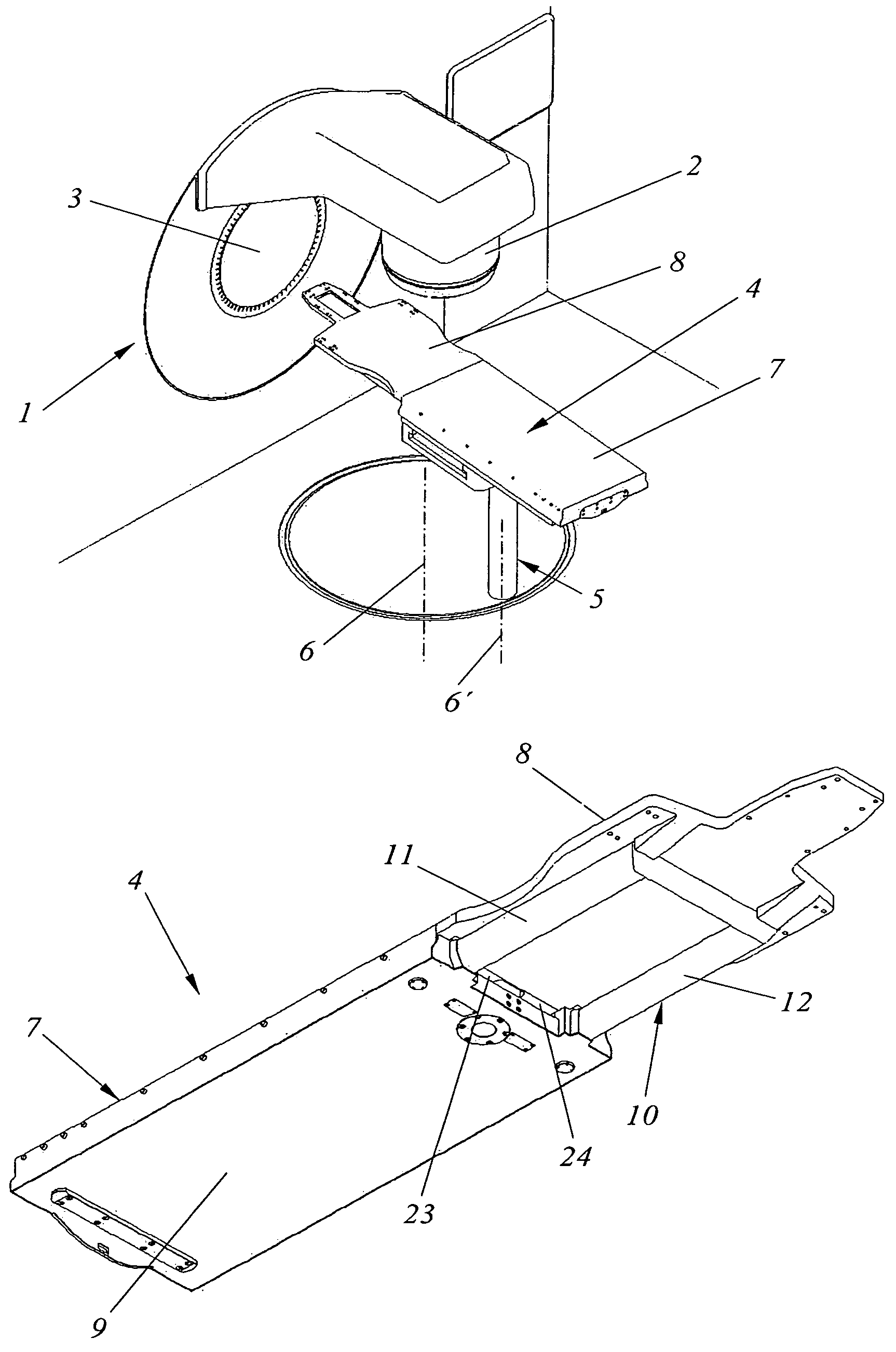
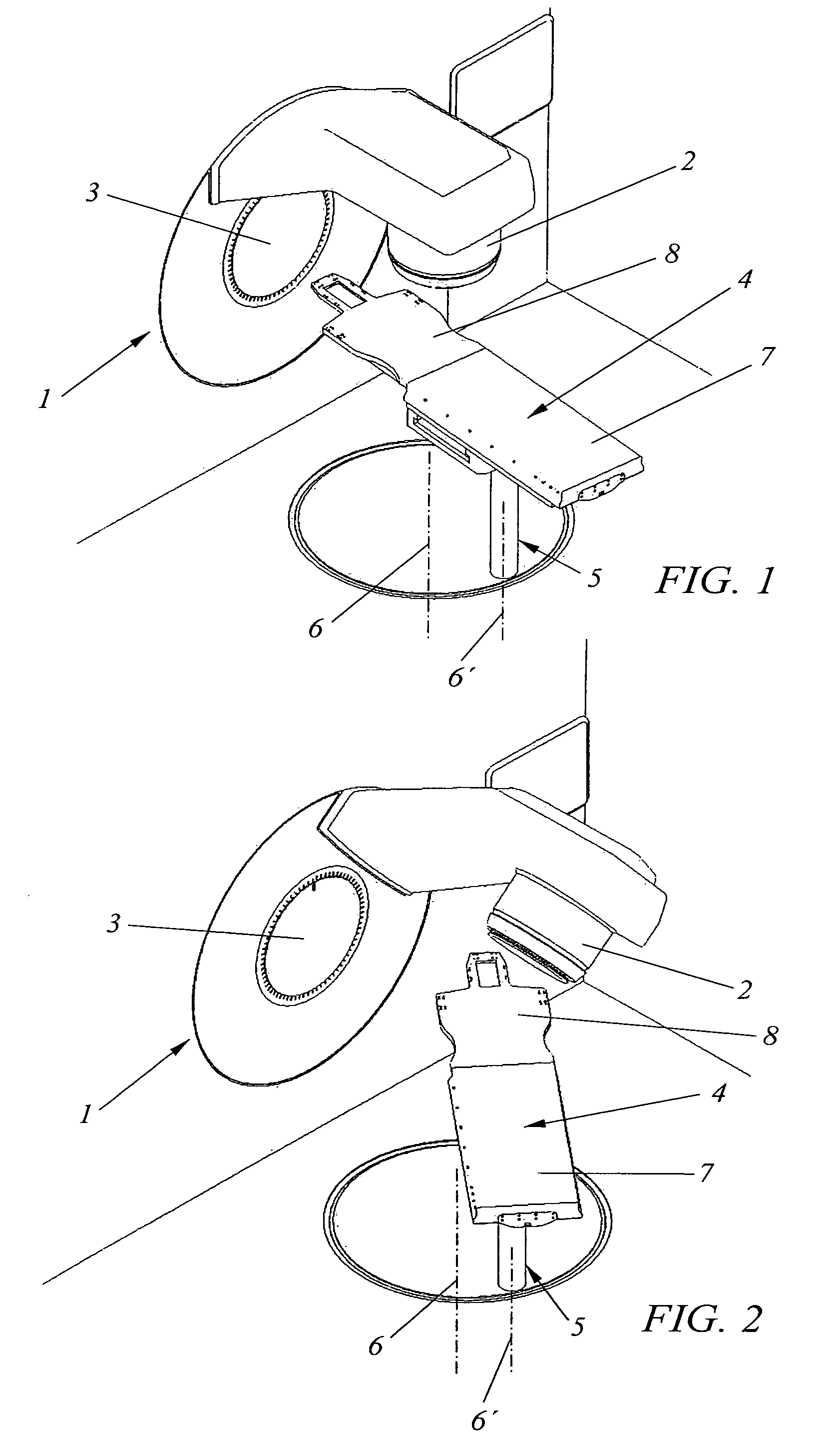
[0028]FIGS. 1, 2 show schematically an arrangement of an irradiation device 1 having an radiating member 2 that can be rotated around a horizontal shaft 3. In this way, the radiating member can be brought into any position in relation to a patient to be irradiated within a range of 360° and therefore in any series of subsequent positions.

[0029]A patient to be treated is supported by a support 4. The support 4 is mounted on an adjustable table 5, which is rotatable around two vertical axes 6, 6′ and is adjustable in height and in which the adjustable table 5 can move the support 4 horizontally and laterally. In this way, the tumor to be treated of a patient can be positioned exactly in the radiation center of radiating member 2. The support 4 comprises a basic portion 7 fixedly applied on the table 5 and a modular portion 8 coupled to said basic portion.

[0030]FIGS. 3, 4 show respectively a plan view and a perspective bottom view of said basic portion 7 of support 4. The basic portion...


PUM


Abstract

The invention relates to a modular patient support system for use with radiotherapy treatments comprising a basic portion to be fixedly mounted and an exchangeable radiotransparent modular portion, said portion to be fixedly mounted being provided with a radiotransparent supporting part intended for supporting an exchangeable modular portion and means being provided for exactly positioning said modular portion in relation to said basic portion and coupling it to said basic portion.

Description

FIELD OF THE INVENTION[0001]The present invention relates to a modular patient support system for use in radiotherapy treatments, at least comprising a radiotransparent structure.BACKGROUND OF THE INVENTION[0002]Such patient supports are known in various embodiments and are substantially intended for being mounted on adjustable tables belonging to an arrangement with irradiation aparatus. With a patient support intended for radiotherapy treatments, rigidity and radiotransparency of said support is of great importance. In all current patient supports, at least a part of the structure comprises metal parts providing rigidity and / or fixation possibilities of accessories. These metal parts cause scatter of the radiation beam. Therefore, with the current patient supports it should always be possible to irradiate past the metal parts. Due to this, it is not possible to irradiate a patient across any desired angle. Further, current supports are often wide, for the purpose of being able to ...

Claims


Application Information

Patent Timeline
Patent Type & Authority Patents(United States)
IPC IPC(8): A61G13/12A61G13/00A61B6/04A61N5/10
CPCA61B6/0442A61B6/4411A61N5/10
Inventor DE MOOY, LEENDERT GERRIT
Owner SINMED
Learn More