Protective device and method of electronic gun beam flow controlling system
A technology of a control system and a protective device, which is applied in the direction of protection against overcurrent, etc., can solve the problems of easy-to-break devices, inability to protect the electronic gun control system, and potential safety hazards, and achieve the effect of improving safety.
- Summary
- Abstract
- Description
- Claims
- Application Information
AI Technical Summary
Problems solved by technology
Method used
Image
Examples
Embodiment 1
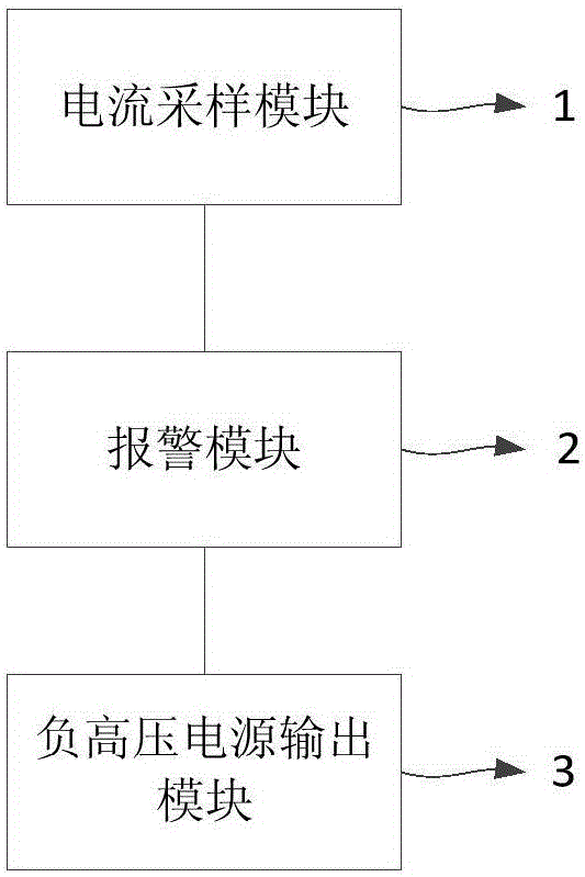
[0020] figure 1 A schematic structural diagram of a protective device for an electron gun beam current control system provided in Embodiment 1 of the present invention. This embodiment is applicable to the case of protecting the electron gun beam current control system. The device can be implemented by means of hardware and / or software accomplish.
[0021] refer to figure 1 The protective device of the electron gun beam current control system provided in this embodiment specifically includes: a current sampling module 1, which is connected to the cathode of the electron gun and the negative high voltage power supply output module 3 respectively, and is used to sample the cathode current of the electron gun to obtain a sampling current; an alarm module 2. Connected to the current sampling module 1, used to judge whether the current circuit sparks according to the sampling current, and output an alarm signal when sparking occurs; the negative high-voltage power supply output mo...
Embodiment 2
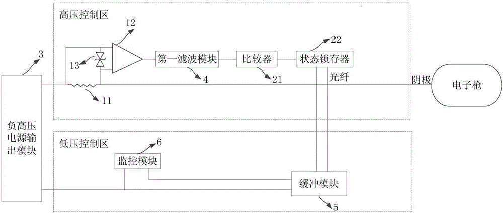
[0026] figure 2 A schematic structural diagram of a protective device for an electron gun beam current control system provided in Embodiment 2 of the present invention. On the basis of the above embodiments, this embodiment preferably further optimizes the current sampling module 1 and the alarm module 2. Refer to figure 2 , including the following:
[0027] Preferably, the current sampling module 1 includes a sampling resistor 11, a differential operational amplifier 12, and a first TVS tube 13 (Transient Voltage Suppressor, transient voltage suppressor diode); one end of the sampling resistor 11 is connected to the cathode of the electron gun, and the other end is connected to the negative electrode. High-voltage power supply output module 3; the two input ends of the differential operational amplifier 12 are connected to the two ends of the sampling resistor 11, and the output end is connected to the alarm module 2; the two ends of the first TVS tube 13 are connected to t...
Embodiment 3
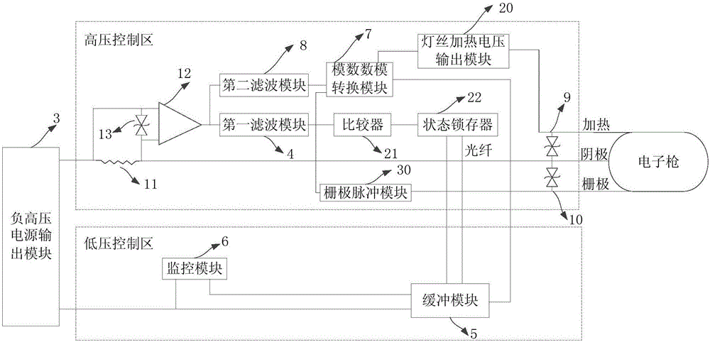
[0042] image 3 A schematic structural diagram of a protective device for an electron gun beam current control system provided by Embodiment 3 of the present invention. On the basis of the above embodiments, this embodiment preferably further adds an analog-to-digital-to-analog conversion module 7. Refer to image 3 , including the following:
[0043] The analog-digital-digital-analog conversion module 7 is connected with the current sampling module 1 and the buffer module 5 respectively, and is used to convert the analog sampling current signal output by the current sampling module 1 into a digital sampling current signal, and send it to the buffer module 5; the buffer module 5 is also used for buffering the digital sampling current signal, and reporting the digital sampling current signal to the monitoring module 6 for monitoring. In this way, the multiplexing of the sampling current is realized to monitor the cathode current, without using a third-party collection tool to ...
PUM
 Abstract
Description
Claims
Application Information
 - Generate Ideas
- Intellectual Property
- Life Sciences
- Materials
- Tech Scout
- Unparalleled Data Quality
- Higher Quality Content
- 60% Fewer Hallucinations
Browse by: Latest US Patents, China's latest patents, Technical Efficacy Thesaurus, Application Domain, Technology Topic, Popular Technical Reports.
© 2025 PatSnap. All rights reserved.Legal|Privacy policy|Modern Slavery Act Transparency Statement|Sitemap|About US| Contact US: help@patsnap.com


