
Urea injection control method based on real-time ammonia storage amount management for catalytic reduction of diesel

A technology of urea injection and control method, which is applied to the electric control of exhaust treatment devices, exhaust treatment, mechanical equipment, etc., which can solve the problems of low NOx conversion efficiency and ammonia leakage, so as to reduce secondary pollution and reduce NOx emissions , The effect of saving the amount of urea injection

Active Publication Date: 2017-06-13
TIANJIN UNIV
View PDF7 Cites 34 Cited by
  • Summary
  • Abstract
  • Description
  • Claims
  • Application Information

AI Technical Summary

Problems solved by technology

[0006] The purpose of the present invention is to overcome the deficiencies in the prior art, aiming at the problem of low NOx conversion efficiency at low temperature of diesel engine aftertreatment SCR system and ammonia leakage under transient working conditions, to provide a diesel engine catalytic reduction based on real-time ammonia storage management The urea injection control method can improve the NO of diesel engine aftertreatment SCR under all working conditions x High conversion efficiency, saving urea consumption and reducing ammonia leakage

Method used


Image

  • Urea injection control method based on real-time ammonia storage amount management for catalytic reduction of diesel
  • Urea injection control method based on real-time ammonia storage amount management for catalytic reduction of diesel
  • Urea injection control method based on real-time ammonia storage amount management for catalytic reduction of diesel

Examples


Embodiment Construction

[0044] The present invention will be described in further detail below in conjunction with the accompanying drawings.

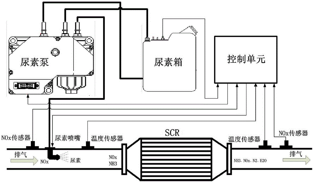
[0045] figure 1 It is a schematic diagram of an SCR system applicable to the present invention, and the SCR system includes an SCR reactor, a urea tank, a urea pump and a control unit. The SCR reactor is equipped with a catalyst carrier, which is NH 3 with NO x The urea tank is loaded with urea required by the SCR system; the urea pump delivers urea to the urea nozzle at a certain pressure; the control unit receives the signal from the SCR system sensor and controls the injection of urea. Equipped with NO upstream of the SCR x sensor, urea nozzle, temperature sensor and pressure sensor, with pressure sensor, temperature sensor and NO x sensor. SCR upstream and downstream NO x Sensors measure NO at SCR inlet and outlet x Mass concentration, the temperature sensor measures the temperature at the inlet and outlet of the SCR, the pressure sensor measures t...


PUM


Abstract

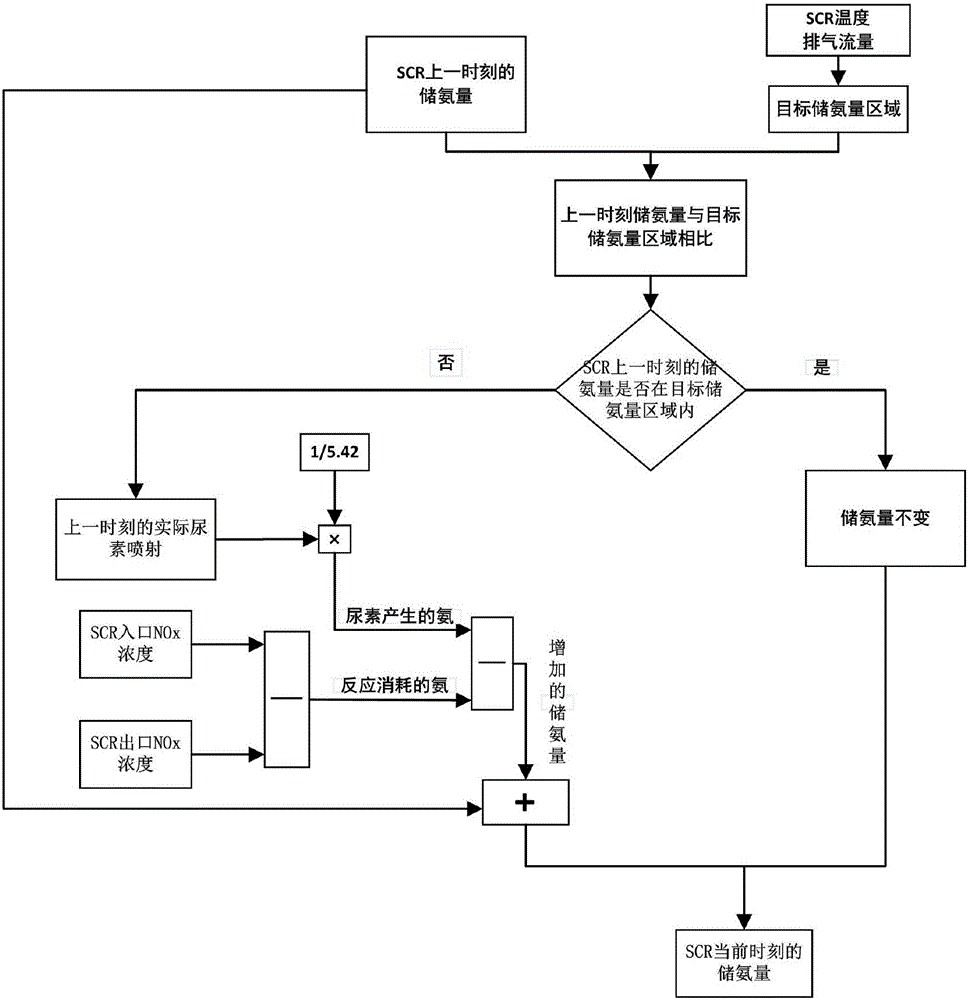
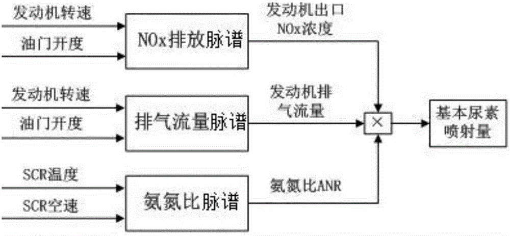
The invention discloses a urea injection control method based on real-time ammonia storage amount management for catalytic reduction of diesel. The method comprises the following steps: an ammonia storage amount calculation model is established according to ammonia mass conservation of an SCR system, and ammonia storage amount of SCR at the current moment in actual working condition is calculated; NOx emission map, an exhaust mass flow map and an ammonia-nitrogen ratio map of an engine are calibrated on the basis of steady-state experiments, and basic urea injection amount is calculated; a target ammonia storage amount area, an ammonia adsorption time constant and an ammonia release time constant are experimentally calibrated, and modified urea injection amount is calculated; urea injection is controlled in the actual working condition on the basis of the sum of the basic urea injection amount and the modified urea injection amount, and slow urea injection and injection stopping are used for assistance under the working condition of sudden increase of exhaust temperature, so that the ammonia storage amount of the SCR at the current moment approaches the target ammonia storage amount area. NOx conversion efficiency in all working conditions of the SCR in aftertreatment of the diesel can be increased, and urea consumption and ammonia leakage are reduced.

Description

technical field [0001] The invention relates to a diesel engine tail gas post-treatment technology, and more specifically relates to a diesel engine catalytic reduction urea injection control method based on real-time ammonia storage management. Background technique [0002] Oxygen-enriched combustion of diesel engines can easily produce higher NO x Emissions, is NO from diesel locomotives x main source of emissions. Selective catalytic reduction technology utilizes the ammonia produced by the hydrolysis of urea to reduce the NO in the tail gas x reduced to N 2 , can reduce more than 90% of NO in diesel engines x , is currently considered to be the solution to diesel NO x Emissions most efficient technology. Compared with EGR technology, the use of SCR post-treatment technology is beneficial to the improvement of fuel economy, and the configuration of the fuel system does not need to be too high, and SCR is less sensitive to sulfur in fuel, and low fuel quality require...

Claims


Application Information

Patent Timeline
IPC IPC(8): F01N9/00F01N3/20
CPCF01N3/208F01N9/00F01N2610/146Y02T10/12Y02T10/40
Inventor 苏万华邬斌扬孙德增刘二喜张顺凯
Owner TIANJIN UNIV
Learn More