
Variable valve timing system

A valve timing and variable technology, applied in the direction of engine components, machines/engines, mechanical equipment, etc., can solve the problems of reducing operating comfort, engine damage, engine jamming, etc., to prevent engine setbacks, small magnetic resistance, The effect of improving comfort

Inactive Publication Date: 2017-06-13
JIANGSU HAILONG ELECTRICAL APPLIANCE
View PDF5 Cites 2 Cited by
  • Summary
  • Abstract
  • Description
  • Claims
  • Application Information

AI Technical Summary

Problems solved by technology

The existing electromagnetic hydraulic valve used in the VVT ​​system can realize the opening and closing of the valve, but it is not stable during the alternating process of opening and closing, and the engine has obvious jams when switching, which is likely to cause engine damage and reduce operating comfort. Spend

Method used


Image

  • Variable valve timing system
  • Variable valve timing system
  • Variable valve timing system

Examples


Embodiment Construction

[0028] Embodiments of the technical solutions of the present invention will be described in detail below in conjunction with the accompanying drawings. The following examples are only used to illustrate the technical solutions of the present invention more clearly, and therefore are only examples, rather than limiting the protection scope of the present invention.

[0029] It should be noted that, unless otherwise specified, the technical terms or scientific terms used in this application shall have the usual meanings understood by those skilled in the art to which the present invention belongs.

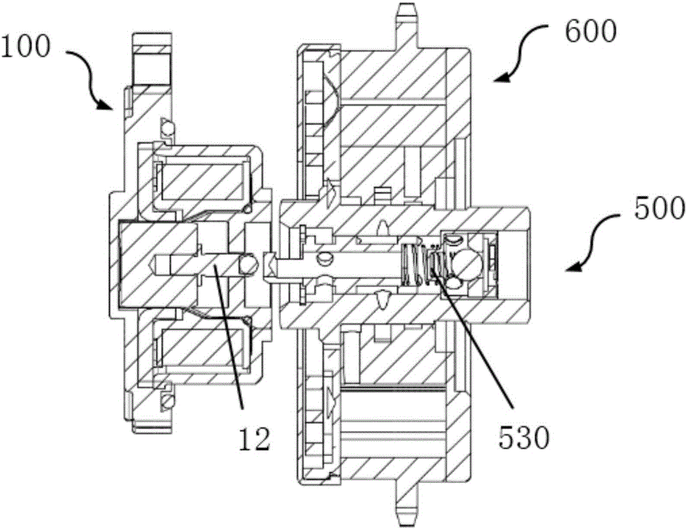
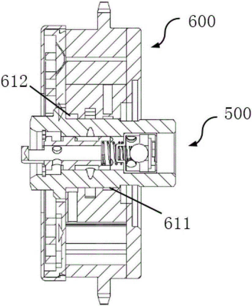
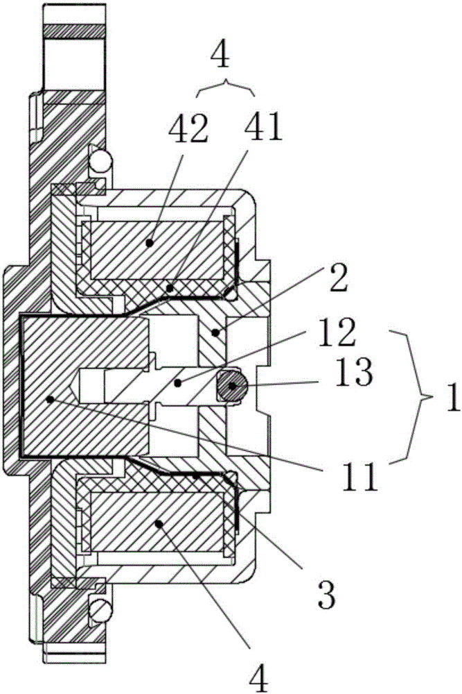
[0030] refer to Figure 1 to Figure 8 , In one embodiment, the present invention provides a variable valve timing system, including: an electromagnet 100, a hydraulic valve 500 and a camshaft adjuster 600;

[0031] The electromagnet 100 includes a coaxial valve core assembly 1, a base 2, a magnetic isolation inner cover 3 and an electromagnetic coil part 4; the electromagnetic coil ...


PUM


Abstract

The invention provides a variable valve timing system, which comprises an electromagnet, a hydraulic valve and a camshaft adjuster, wherein the electromagnet comprises a valve core assembly, a substrate, a magnetic-isolating inner cover and an electromagnetic coil part which are coaxially arranged; the electromagnetic coil part comprises a skeleton and a coil; the skeleton sleeves the outside of the magnetic-isolating inner cover; the coil is wound on the skeleton; the valve core assembly and the substrate are arranged in the magnetic-isolating inner cover along the axial direction; the valve core assembly comprises a valve core and a post rod connected to the valve core; a conical part with an outer conical surface is arranged at one end, close to the valve core, of the substrate, and an accommodating part for accommodating the valve core is arranged at the end; a guide through hole is also arranged in the axis of the substrate; and the post rod is arranged in the guide through hole in a sliding manner. The variable valve timing system provided by the invention is stable in operation and high in reliability.

Description

technical field [0001] The invention relates to the field of automobile engines, in particular to a variable valve timing system of the engine. Background technique [0002] Variable valve timing technology (VVT) is to adjust the phase of the camshaft through the camshaft adjuster under specific engine conditions, and control the advance and delay of the opening angle of the intake valve to adjust the intake and exhaust volume and timing and change the valve The size of the overlapping angle is used to increase the intake charge and efficiency, better organize the intake swirl, adjust the cylinder explosion pressure and residual exhaust gas volume, and obtain engine power, torque, emission, fuel economy, comfort, etc. Improvement of performance, thereby solving the technical contradiction of mutual restriction among various performance indicators of traditional fixed valve timing engines. [0003] The spool of the solenoid valve in the variable valve timing system moves acc...

Claims


Application Information

Patent Timeline
Patent Type & Authority Applications(China)
IPC IPC(8): F01L1/34
CPCF01L1/3442F01L2001/3443
Inventor 张宪朱圣明
Owner JIANGSU HAILONG ELECTRICAL APPLIANCE
Learn More