Soil nailing wall supporting structure and construction method

A technology for supporting structures and soil nailing walls, which can be used in foundation structure engineering, excavation, sheet pile walls, etc., can solve the problems of difficult strength and large influence of welding points, and achieve weak shear resistance, long life and corrosion resistance strong effect

Inactive Publication Date: 2017-06-13
HUAIBEI YUXIN NEW MATERIAL
View PDF7 Cites 3 Cited by
  • Summary
  • Abstract
  • Description
  • Claims
  • Application Information

AI Technical Summary

Problems solved by technology

[0004] The purpose of the present invention is to solve the defects in the prior art that the soil nail wall has a great influence on the adjacent underground engineering and the strength of the welding point is difficult to meet the design stress requirements, and to provide a soil nail wall support structure to solve the above problems

Method used


Image

  • Soil nailing wall supporting structure and construction method
  • Soil nailing wall supporting structure and construction method

Examples


Embodiment 1

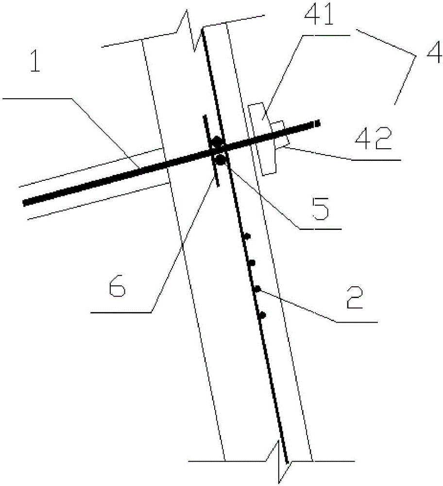
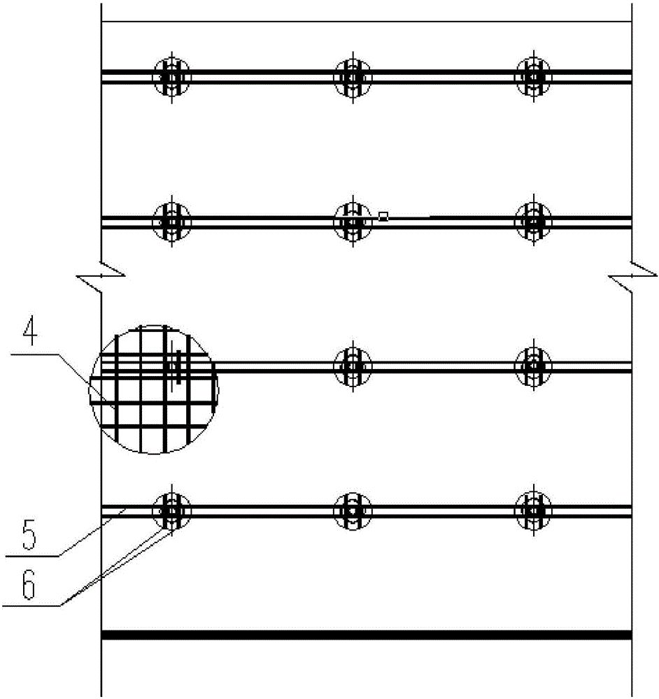
[0023] according to figure 1 , figure 2 As shown, a soil nail wall support structure includes a number of deep holes opened on the required support surface, and generally a number of deep holes are arranged in an array. Pierce the GFRP bar 1 in the deep hole and grout to form a soil nail body. Hang the reinforcement mesh 2 on the support surface; the reinforcement mesh 2 is fixed with the rod body of each GFRP bar 1 exposed to the support surface, and the reinforcement mesh 2 is sprayed to form the concrete surface layer 3 of the support surface; the outer end of the GFRP bar 1 is exposed The concrete surface layer 3 forms an anchoring end, and the soil nail body and the concrete surface layer 3 form a whole through the cooperation of the anchoring part 4 and the anchoring end of the GFRP bar 1 .

[0024] In order for several independent GFRP bars 1 to form a whole, the GFRP bars 1 in the same row are clamped up and down by two transverse bars 5 to form a whole, and short b...

Embodiment 2

[0028] The construction method of soil nail wall support structure comprises the following steps:

[0029] Drill the hole first, and then clean the hole after drilling to the set depth, then insert the GFRP bar 1 into the deep hole and grout to form the soil nail body. The cross bar 5 is clamped to form a whole, and then the grid is connected to the grid and sprayed concrete, and finally the concrete surface layer is formed. After the concrete surface layer 3 is cured to the set strength, the GFRP tendon 1 is extended out of the concrete surface layer 3 through the anchor plate. segment anchoring, so that the soil nail body and the concrete surface layer 3 form a whole.


PUM


Abstract

The invention provides a soil nailing wall supporting structure and a construction method. The construction method comprises the steps as follows: a plurality of deep holes are formed in a to-be-supported surface, GFRP (glass fiber reinforced plastic) ribs penetrate through the deep holes, grouting is performed, and soil nailing bodies are formed; reinforcing meshes are hung on the supported surface; the reinforcing meshes are fixed with rod pieces, exposed out of the supported surface, of all GFRP ribs, and a concrete surface layer of the supported surface is formed by performing guniting on the reinforcing meshes; outer ends of the GFRP ribs are exposed out of the concrete surface layer to form anchoring ends, and the soil nailing bodies and the concrete surface layer form a whole through cooperation of anchoring parts and the anchoring ends of the GFRP ribs. Compared with the prior art, the GFRP ribs have higher tensile strength, can improve the overall support performance of a soil nailing wall after being applied to the soil nailing wall and are stable in performance, high in corrosion resistance and long in service life. More importantly, the GFRP ribs have weak shear capacity and can be cut off easily when nearby underground engineering construction is interfered by the soil nailing wall, and a lot of manpower and material resources are saved.

Description

technical field [0001] The invention relates to the technical field of slope protection, in particular to a soil nail wall support structure and a construction method. Background technique [0002] Compared with the "pile + inner support system", the "pile-anchor system" in slope support has the advantages of simple construction, cost saving and shortened construction period. The traditional "steel and steel strand" anchor body has high shear strength, and the "out of bounds" of the anchor will have cross-effects on underground projects such as excavation of adjacent land, pile foundation engineering, subway, and pipeline shield construction , are greatly restricted in practical engineering. [0003] In the traditional reinforced soil nailed wall, the reinforced soil nail and the steel mesh in the injection layer on the surface of the soil nailed wall are connected by welding. Since the soil nailed steel bar and the hanging mesh steel bar are in a vertical relationship and ...

Claims


Application Information

Patent Timeline
IPC IPC(8): E02D17/20E02D5/76
CPCE02D17/20E02D5/765E02D2300/0006
Inventor 李泉崔志军孙佰川
Owner HUAIBEI YUXIN NEW MATERIAL
Why Eureka
Try Eureka