High-efficient denitriding reactor of continuous flow
A reactor and denitrification technology, applied in the field of high-efficiency denitrification reactors, can solve the problems of high COD load, anaerobic ammonia oxidation can not be carried out, interfere with precipitation effluent, etc., and achieve the effect of high COD load
- Summary
- Abstract
- Description
- Claims
- Application Information
AI Technical Summary
Problems solved by technology
Method used
Image
Examples
Embodiment 1
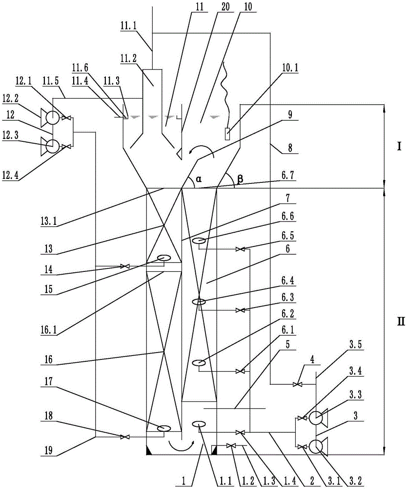
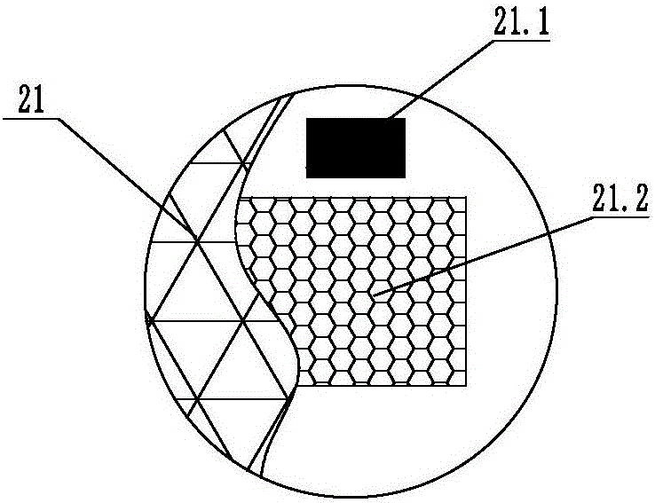
[0049] Such as figure 1 As shown, a continuous-flow high-efficiency denitrification reactor includes a reactor body. The reactor body is sequentially provided with a separation zone I and a reaction zone II from top to bottom. Divided into left and right half areas, the left half area is the water outlet area 11, the right half area is the gas release area 10, the upper part of the water outlet area 11 is provided with an overflow weir 11.3, and the overflow weir 11.3 and the inner wall of the water outlet area 11 form an overflow tank 11.6 , the bottom of the overflow tank 11.6 is provided with an outlet pipe 11.4; the reaction zone II is provided with a medial septum Ⅰ7 to divide the reaction zone II into two halves, the left and right halves, the medial septum Ⅰ7 and the medial septum Ⅱ 20 are located on the same plane and are not connected. Ⅰ7 is provided with a deflector 9, and the deflector 9 forms a diversion channel I with the medial septum II20. The water outlet area ...
Embodiment 2
[0054] like figure 1 As shown, a continuous-flow high-efficiency denitrification reactor includes a reactor body. The reactor body is sequentially provided with a separation zone I and a reaction zone II from top to bottom. Divided into left and right half areas, the left half area is the water outlet area 11, the right half area is the gas release area 10, the upper part of the water outlet area 11 is provided with an overflow weir 11.3, and the overflow weir 11.3 and the inner wall of the water outlet area 11 form an overflow tank 11.6 , the bottom of the overflow tank 11.6 is provided with an outlet pipe 11.4; the reaction zone II is provided with a medial septum Ⅰ7 to divide the reaction zone II into two halves, the left and right halves, the medial septum Ⅰ7 and the medial septum Ⅱ 20 are located on the same plane and are not connected. Ⅰ7 is provided with a deflector 9, and the deflector 9 forms a diversion channel I with the medial septum II20. The water outlet area 11 ...
Embodiment 3
[0060] like figure 1 As shown, a continuous-flow high-efficiency denitrification reactor includes a reactor body. The reactor body is sequentially provided with a separation zone I and a reaction zone II from top to bottom. Divided into left and right half areas, the left half area is the water outlet area 11, the right half area is the gas release area 10, the upper part of the water outlet area 11 is provided with an overflow weir 11.3, and the overflow weir 11.3 and the inner wall of the water outlet area 11 form an overflow tank 11.6 , the bottom of the overflow tank 11.6 is provided with an outlet pipe 11.4; the reaction zone II is provided with a medial septum Ⅰ7 to divide the reaction zone II into two halves, the left and right halves, the medial septum Ⅰ7 and the medial septum Ⅱ 20 are located on the same plane and are not connected. Ⅰ7 is provided with a deflector 9, and the deflector 9 forms a diversion channel I with the medial septum II20. The water outlet area 11 ...
PUM
 Abstract
Description
Claims
Application Information
 - R&D Engineer
- R&D Manager
- IP Professional
- Industry Leading Data Capabilities
- Powerful AI technology
- Patent DNA Extraction
Browse by: Latest US Patents, China's latest patents, Technical Efficacy Thesaurus, Application Domain, Technology Topic, Popular Technical Reports.
© 2024 PatSnap. All rights reserved.Legal|Privacy policy|Modern Slavery Act Transparency Statement|Sitemap|About US| Contact US: help@patsnap.com


