Eureka AIR delivers breakthrough ideas for toughest innovation challenges, trusted by R&D personnel around the world.

Novel new energy vehicle charging equipment

A technology for new energy vehicles and charging equipment, applied in electric vehicle charging technology, charging stations, electric vehicles, etc., can solve problems such as poor plug stability, potential safety hazards, waste of power resources, etc., to prevent electric shock accidents and have a simple structure. , the effect of high safety

Active Publication Date: 2017-06-13
迈思普电子股份有限公司
View PDF4 Cites 36 Cited by
  • Summary
  • Abstract
  • Description
  • Claims
  • Application Information

AI Technical Summary

Problems solved by technology

The development of electric vehicles is inseparable from charging stations that supplement electric energy. Traditional charging piles need to be plugged in manually. The plugging stability is poor, time-consuming and laborious, and there are potential safety hazards. When connecting work, it is necessary to control the automatic plug-in operation of the propulsion equipment after the mains power is energized, resulting in waste of power resources

Method used


Image

  • Novel new energy vehicle charging equipment
  • Novel new energy vehicle charging equipment
  • Novel new energy vehicle charging equipment

Examples


Embodiment Construction

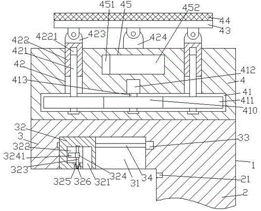
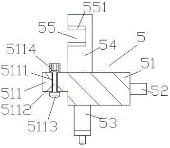
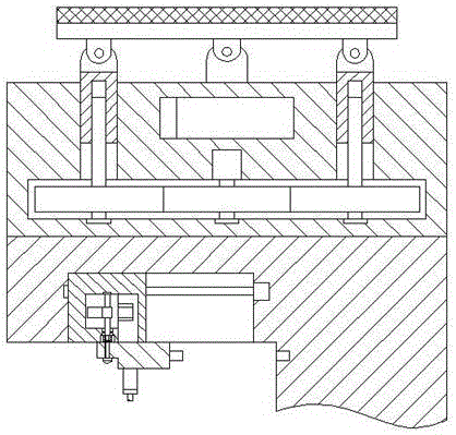
[0026] Such as Figure 1-Figure 9 As shown, a new type of new energy vehicle charging device of the present invention includes a pile body 1, a solar power collection mechanism 4 fixedly installed on the top end surface of the pile body 1, and a charging gun 5. The pile body 1 is supported by a support portion 2 and a propulsion part 3, the bottom end surface of the propulsion part 3 is provided with a propulsion groove 31, and the propulsion groove 31 is provided with a first screw 34 extending left and right, and the right end of the first screw 34 is connected with the first motor 33 power connection, the first motor 33 is provided with a support device, and the support device includes a shock absorber 332 and a heat dissipation fin 331, and the push groove 31 is provided with a threaded connection with the first screw rod 34 Propelling block 32, said propelling block 32 is provided with a first cavity 322, said propelling block 32 on the right side of said first cavity 322...


PUM


Abstract

The invention discloses novel new energy vehicle charging equipment which comprises a pile, a solar electricity collecting mechanism and a charging gun. The solar electricity collecting mechanism is fixedly mounted on an end surface of the top of the pile, the pile comprises a support portion and a push portion, a push groove is formed in an end surface of the bottom of the push portion, a first screw which extends in the left-right direction is arranged in the push groove, an end of the right side of the first screw is in power connection with a first motor, a protective support device is arranged outside the first motor and comprises a damping plate and radiating fins, a push block which is fittingly connected with the first screw in a threaded manner is arranged in the push groove, a first cavity is arranged in the push block, a locking groove is formed in the push block and is positioned on the right side of the first cavity, the bottom of the locking groove is perforated through the end surfaces of the bottom of the push block, the ends of the right side of the first cavity are communicated with the upper left side of the locking groove, a countersunk groove is formed in an end surface of the bottom of the push block and is positioned at the bottom of the first cavity, and a first rotary shaft which extends in the up-down direction is arranged in the first cavity. The novel new energy vehicle charging equipment has the advantages that the novel new energy vehicle charging equipment is simple in structure and high in safety, can be operated conveniently and quickly and is environmentally friendly, charging insertion can be automatically controlled, power can be generated and supplied by the aid of solar energy, and accordingly energy can be saved.

Description

technical field [0001] The invention relates to the technical field of new energy vehicle charging, in particular to a new type of new energy vehicle charging equipment. Background technique [0002] With the low-carbon economy becoming the main theme of my country's economic development, electric vehicles can reduce oil consumption and reduce polluting gas emissions, and have become a vigorously developed industry in my country. The electric vehicle charging station provides energy supply for the operation of electric vehicles and is a necessary supply facility for the development of electric vehicles. The development of electric vehicles is inseparable from charging stations that supplement electric energy. Traditional charging piles need to be plugged in manually. The plugging stability is poor, time-consuming and laborious, and there are potential safety hazards. When connecting work, it is necessary to control the automatic plugging operation of the propulsion equipmen...

Claims


Application Information

Patent Timeline
IPC IPC(8): B60L11/18
CPCB60L53/14B60L53/31B60L53/51Y02T10/70Y02T10/7072Y02T90/12Y02T90/14
Inventor 郑晓春
Owner 迈思普电子股份有限公司
Why Eureka
Eureka Blog
Learn More