Eureka AIR delivers breakthrough ideas for toughest innovation challenges, trusted by R&D personnel around the world.

Volumetric flask cleaning device

A technology of cleaning device and volumetric flask, which is applied in the field of chemical experiment utensils to achieve the effects of saving manpower, improving cleaning efficiency and cleanliness, and saving water resources

Inactive Publication Date: 2017-06-13
周博雯
View PDF1 Cites 23 Cited by
  • Summary
  • Abstract
  • Description
  • Claims
  • Application Information

AI Technical Summary

Problems solved by technology

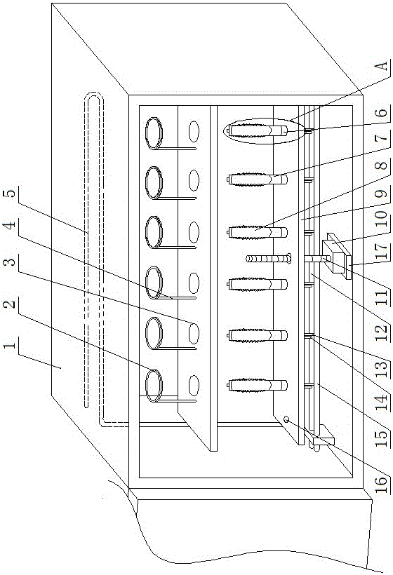
[0005] The technical task of the present invention is to provide a volumetric flask cleaning device for the above deficiencies, to solve the existing problem of how to flush the outer walls of multiple volumetric flasks at one time and brush the inner walls of the volumetric flasks

Method used


Image

  • Volumetric flask cleaning device
  • Volumetric flask cleaning device
  • Volumetric flask cleaning device

Examples


Embodiment 1

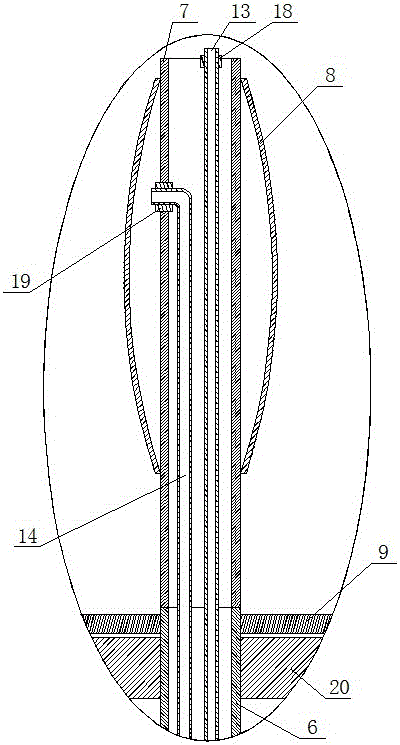
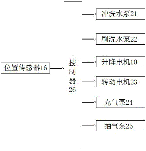
[0029] As attached figure 1 , Attached figure 2 And image 3 As shown, a volumetric flask cleaning device of the present invention includes a box body 1 and a bracket, a washing device, and a scrubbing device located in the box body 1. The bracket includes a support plate and a plurality of fixing rings 2 fixed on the support plate, and supports A plurality of flushing through holes are opened on the plate, and each flushing through hole is provided with a fixing rod 4, and the top of the fixing rod 4 is fixed with a fixing ring 2. The fixing ring 2 is coaxial with the corresponding flushing through hole. The diameter of the ring 2 is larger than the diameter of the neck of the volumetric flask and smaller than the diameter of the bottom of the volumetric flask, so that the fixing ring 2 and the flushing through hole can fix the inverted volumetric flask on the support plate; the flushing device is fixed on the fixing ring 2 Above, the scrubbing device is fixed below the suppor...

Embodiment 2

[0055] As attached Figure 4 As shown, this embodiment is a further improvement on the basis of Embodiment 1. The difference between this embodiment and Embodiment 1 is:

[0056] In view of the fact that the volumetric flask is prone to shaking when the volumetric flask is rinsed and scrubbed, a vertical rod 28 is fixed at each flushing through hole on the support plate, and a fixing clip 27 is fixed at the top of the vertical rod 28. The fixing clip 27 The clamping diameter can accommodate the bottleneck of the volumetric flask.

[0057] In the process of flushing and scrubbing the volumetric flask in the tank 1, water will remain in the tank 1. In order to facilitate the timely drainage of the water in the tank 1, a water outlet hole is opened at the bottom of the tank 1, and the water is discharged. A water outlet pipe 29 is connected to the through hole, and water can flow out through the water outlet pipe 29 after flushing in the tank body 1.

[0058] The working process of a ...


PUM


Abstract

The invention discloses a cleaning device for volumetric flasks, which belongs to the field of chemical experiment equipment. The technical problem to be solved is how to wash the outer walls of multiple volumetric flasks at one time and brush the inner walls of the volumetric flasks; its structure includes a box body and The bracket, the flushing device and the brushing device located in the box, the bracket includes a support plate and a plurality of fixing rings fixed on the support plate, a plurality of flushing through holes are opened on the support plate, and each flushing through hole corresponds to a fixing ring , the diameter of the fixed ring is greater than the diameter of the bottleneck of the volumetric flask and less than the diameter of the bottle bottom of the volumetric flask, the fixed ring and the flushing through hole cooperate to fix the inverted volumetric flask on the support plate; the flushing device is fixed on the fixed ring Above, the flushing device is used to flush the outer wall of the volumetric flask from above, the scrubbing device is fixed below the support plate, and the scrubbing device is used to scrub the inner wall of the volumetric flask from below, both the flushing device and the scrubbing device are connected to the controller.

Description

Technical field [0001] The invention relates to the field of chemical experiment appliances, in particular to a volumetric flask cleaning device. Background technique [0002] The volumetric flask is a thin-necked pear-shaped flat-bottomed volumetric device with a ground glass stopper. There is a marking on the neck, indicating that the solution is tangent to the marking of the bottleneck of the volume at the specified temperature. The volume is exactly equal to the volume marked on the bottle. In chemical experiments, the volumetric flask is a commonly used instrument. In view of the slender neck of the volumetric flask and the pear-shaped bottom of the flask, it is difficult to clean the volumetric flask with a small head cleaning brush. The inner wall of the part is cleaned. When using a large-head cleaning brush, the bottleneck is too thin and the cleaning brush is not easy to enter. [0003] The Chinese patent published on October 21, 2015 with the publication number CN 1049...

Claims


Application Information

Patent Timeline
IPC IPC(8): B08B9/087B08B9/093
CPCB08B9/087B08B9/093
Inventor 周博雯
Owner 周博雯
Why Eureka
Eureka Blog
Learn More