Potentiometer and combination device of potentiometer and cooker ignition switch

An ignition switch and combination device technology, applied in the field of potentiometers, can solve the problems of poor accuracy, single function, and limited application of potentiometers, and achieve the effects of improving accuracy, wide application and simple structure

Active Publication Date: 2017-06-09
FOSHAN VIOMI ELECTRICAL TECH +1
View PDF5 Cites 2 Cited by
  • Summary
  • Abstract
  • Description
  • Claims
  • Application Information

AI Technical Summary

Problems solved by technology

[0002] Existing potentiometers have many styles but single functions. The structure includes a housing, a rotating shaft, a brush, a power supply terminal and a position signal terminal. The brush is arranged on the rotating shaft, and the housing is provided with a brush sliding area. The brush is driven by the rotating shaft Sliding contact along the brush sliding area, the brush sliding area has resistance from the starting point, or a better potentiometer will also reserve a starting point without resistance area, but the above structure has the following disadvantages: (1) The potentiometer rotates When adjusting, due to the conduction of the brush, it cannot be transformed from infinite resistance to zero point, which is not conducive to the identification of product signal output, and its accuracy is also poor, resulting in many restrictions on the application of potentiometers, which is not conducive to the promotion and use of products

Method used


Image

  • Potentiometer and combination device of potentiometer and cooker ignition switch

Examples


Embodiment Construction

[0021] The present invention will be further described below in conjunction with the accompanying drawings and embodiments.

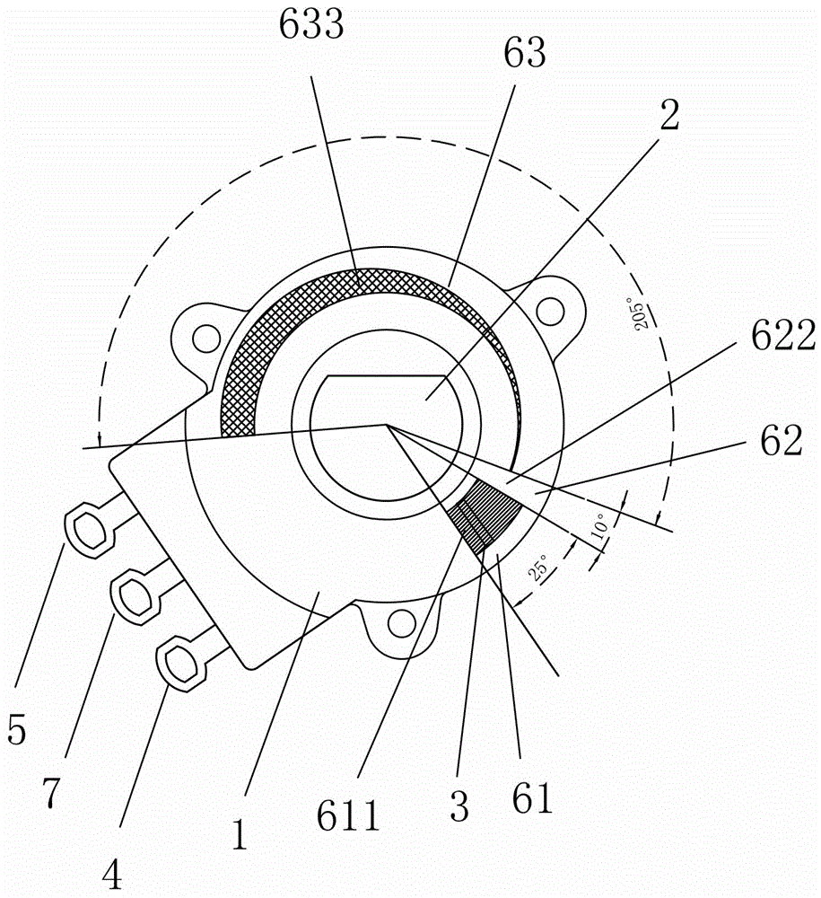
[0022] like figure 1 As shown, a potentiometer includes a housing 1, a rotating shaft 2, a brush 3, a power supply terminal 4, a position signal terminal 5, and a grounding terminal 7. The brush 3 is arranged on the rotating shaft 2. It is characterized in that, on the housing 1 A brush sliding area 6 is provided. The brush sliding area 6 includes a brush non-conduction area 61, a brush conduction waiting area 62 and a brush conduction variable resistance area 63 along the direction from the starting point to the end point. The brush 3 slides with the brush under the drive of the rotating shaft 2. The area 6 slides in contact, the power terminal 4 and the position signal terminal 5 are respectively connected between the brush 3 and the brush sliding area 6 , and the ground terminal 7 , the power terminal 4 and the position signal terminal 5 are all set ...


PUM

PropertyMeasurementUnit
Central angleaaaaaaaaaa

Abstract

The invention discloses a potentiometer which comprises a housing, a rotating shaft, a brush and the like, wherein a brush sliding region is arranged on the housing; the brush sliding region comprises a brush non-conducting region, a brush conduction waiting region and a brush conducting variable-resistance region from a starting point to an end point; the brush is driven by the rotating shaft to be in sliding contact with a brush contact region; a power supply end and a position signal end are respectively connected between the brush and the brush sliding region. The potentiometer does not produce current within a certain angle range behind the starting point position, to avoid that the potentiometer keeps consuming current when the potentiometer does not return to the starting point at gap operation; the brush is conducted and converted from infinite resistance to zero, which is beneficial for the identification of product signal output; the potentiometer has relatively good accuracy, is widely applied, and is beneficial for popularization and use of products. The invention further discloses a combination device of the potentiometer and a cooker ignition switch, wherein the combination device is simple in structure and easy to operate, and is beneficial for accurately outputting a firepower regulating signal of the cooker ignition switch.

Description

technical field [0001] The invention relates to the technical field of potentiometers, in particular to a potentiometer and a combined device of the potentiometer and an ignition switch of a cooker. Background technique [0002] Existing potentiometers have many styles but single functions. The structure includes a housing, a rotating shaft, a brush, a power supply terminal and a position signal terminal. The brush is arranged on the rotating shaft, and the housing is provided with a brush sliding area. The brush is driven by the rotating shaft Sliding contact along the brush sliding area, the brush sliding area has resistance from the starting point, or a better potentiometer will also reserve a starting point without resistance area, but the above structure has the following disadvantages: (1) The potentiometer rotates When adjusting, due to the conduction of the brush, it cannot be transformed from infinite resistance to zero point, which is not conducive to the identific...

Claims


Application Information

Patent Timeline
IPC IPC(8): H01C10/34F24C3/10F24C3/12
CPCF24C3/103F24C3/126H01C10/34
Inventor 陈小平
Owner FOSHAN VIOMI ELECTRICAL TECH
Why Eureka
Try Eureka