
Positive semi-definite relaxation time difference positioning method for distributed multi-point positioning monitoring system

A semi-positive definite relaxation, multi-point positioning technology, used in positioning, radio wave measurement systems, and re-radiation, etc., can solve the problems of high nonlinearity, local convergence and divergence, and easy occurrence of false targets in the time difference positioning method.

Inactive Publication Date: 2017-06-09
ANHUI SUN CREATE ELECTRONICS
View PDF2 Cites 14 Cited by
  • Summary
  • Abstract
  • Description
  • Claims
  • Application Information

AI Technical Summary

Problems solved by technology

In the process of maintaining the airport surface surveillance radar, equipment maintenance personnel include the following three problems: aircraft target splitting, certain blind spots, and false targets are prone to appear
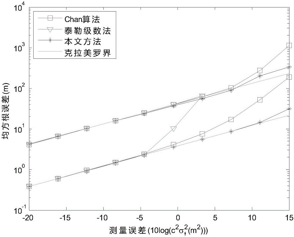
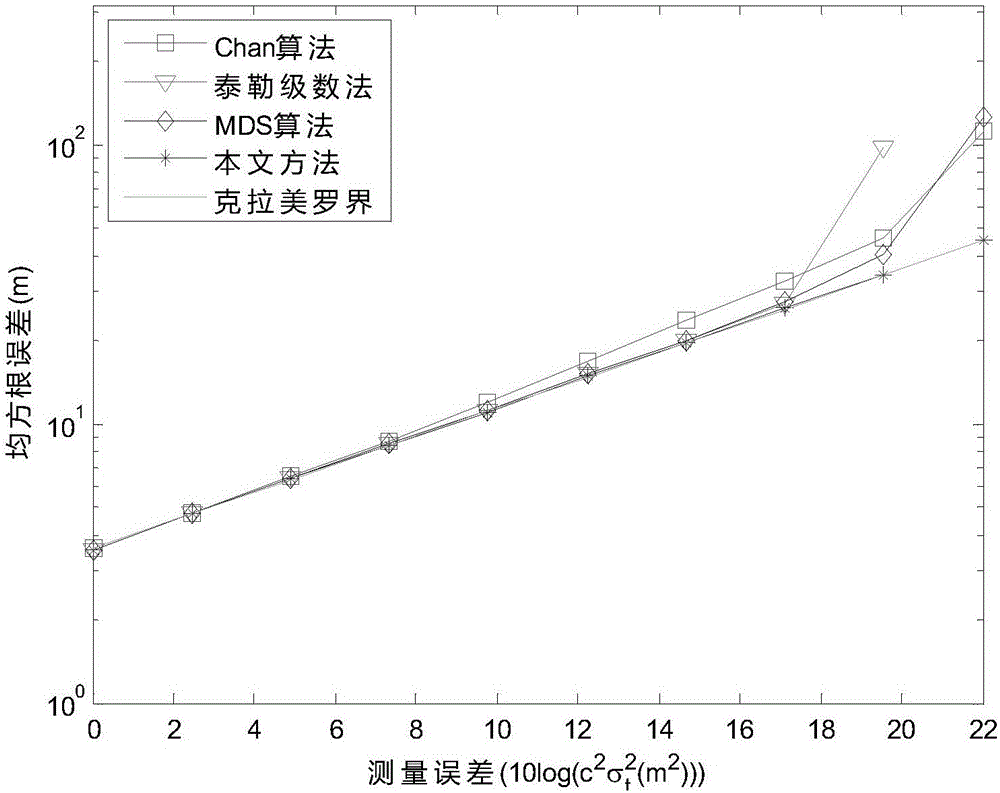
[0004] The traditional semi-positive definite relaxation time difference positioning method usually uses Taylor series algorithm, Chan algorithm, and MDS algorithm to determine the position information of the target. Using the Taylor series algorithm has requirements for the selection of the initial value of the iteration, and there will be local convergence or divergence; The Chan algorithm and the MDS algorithm lead to inaccurate judgment of the position of the signal source when the measurement error is large, which leads to highly nonlinear problems in the time difference positioning method

Method used


Image

  • Positive semi-definite relaxation time difference positioning method for distributed multi-point positioning monitoring system
  • Positive semi-definite relaxation time difference positioning method for distributed multi-point positioning monitoring system
  • Positive semi-definite relaxation time difference positioning method for distributed multi-point positioning monitoring system

Examples


Embodiment Construction

[0051] The following will clearly and completely describe the technical solutions in the embodiments of the present invention with reference to the accompanying drawings in the embodiments of the present invention. Obviously, the described embodiments are only some, not all, embodiments of the present invention. Based on the embodiments of the present invention, all other embodiments obtained by persons of ordinary skill in the art without making creative efforts belong to the protection scope of the present invention.

[0052] The semi-positive definite relaxation time difference positioning method used in the distributed multipoint positioning monitoring system is a very important step in the time difference positioning method. The specific steps of the time difference positioning method include: firstly, the main station of the target receiving station in the distributed multipoint positioning monitoring system and The auxiliary station of the receiving station obtains the t...


PUM


Abstract

The invention belongs to the real time positioning technical field of a distributed multi-point positioning monitoring system, and especially relates to a positive semi-definite relaxation time difference positioning method for the distributed multi-point positioning monitoring system; the method comprises the following steps: firstly building a time difference positioning equation; carrying out maximum likelihood estimation for a signal source position, i.e., a to-be-positioned object position; importing an auxiliary vector; converting a distance difference positioning equation into a constraint least square problem; carrying out weight least square solving for the auxiliary vector; using the weight least square solved auxiliary vector to primarily estimate relaxation equality constraint, and building a novel cost function; using a protruding positive semi-definite program to optimize and solve the auxiliary vector value and a variable value transpositioned by the auxiliary vector; using a characteristic constant to decompose the obtained auxiliary vector value; finally obtaining the signal source position information according to a relation between the solved auxiliary vector value and the signal source position. The method can prevent the local convergence and solving divergence problems caused by a conventional iteration algorithm, thus improving the positioning precision.

Description

technical field [0001] The invention belongs to the technical field of real-time positioning of a distributed multi-point positioning monitoring system, in particular to a semi-positive definite relaxation time difference positioning method for a distributed multi-point positioning monitoring system. Background technique [0002] With the rapid development of my country's economy, the number of flights is also increasing rapidly, which puts forward higher requirements for the command of the air traffic control system controller and the maintenance of facilities and equipment. The airport surface surveillance radar is a radar, mainly used to monitor the airport scene Aircraft and vehicles use the target's own radiation or reflection characteristics of electromagnetic waves to find targets. In the process of maintaining the airport surface surveillance radar, equipment maintenance personnel include the following three problems: aircraft target splitting, certain blind spots, an...

Claims


Application Information

Patent Timeline
IPC IPC(8): G01S13/74G01S7/02G01S5/02
CPCG01S5/02G01S7/02G01S13/74
Inventor 杨琳徐瑾刘锐马磊崔扬
Owner ANHUI SUN CREATE ELECTRONICS
Learn More