Frozen sample preparation device for scanning electron microscope
A scanning electron microscope and impact device technology, which is used in the preparation of test samples, measuring devices, sampling, etc., can solve the problems of difficulty in ensuring the low temperature environment of the sample, complicated operation process, and unsuitable for large-scale sample preparation requirements. Avoid low temperature damage, low cost, fully functional effect
- Summary
- Abstract
- Description
- Claims
- Application Information
AI Technical Summary
Problems solved by technology
Method used
Image
Examples
Embodiment 1
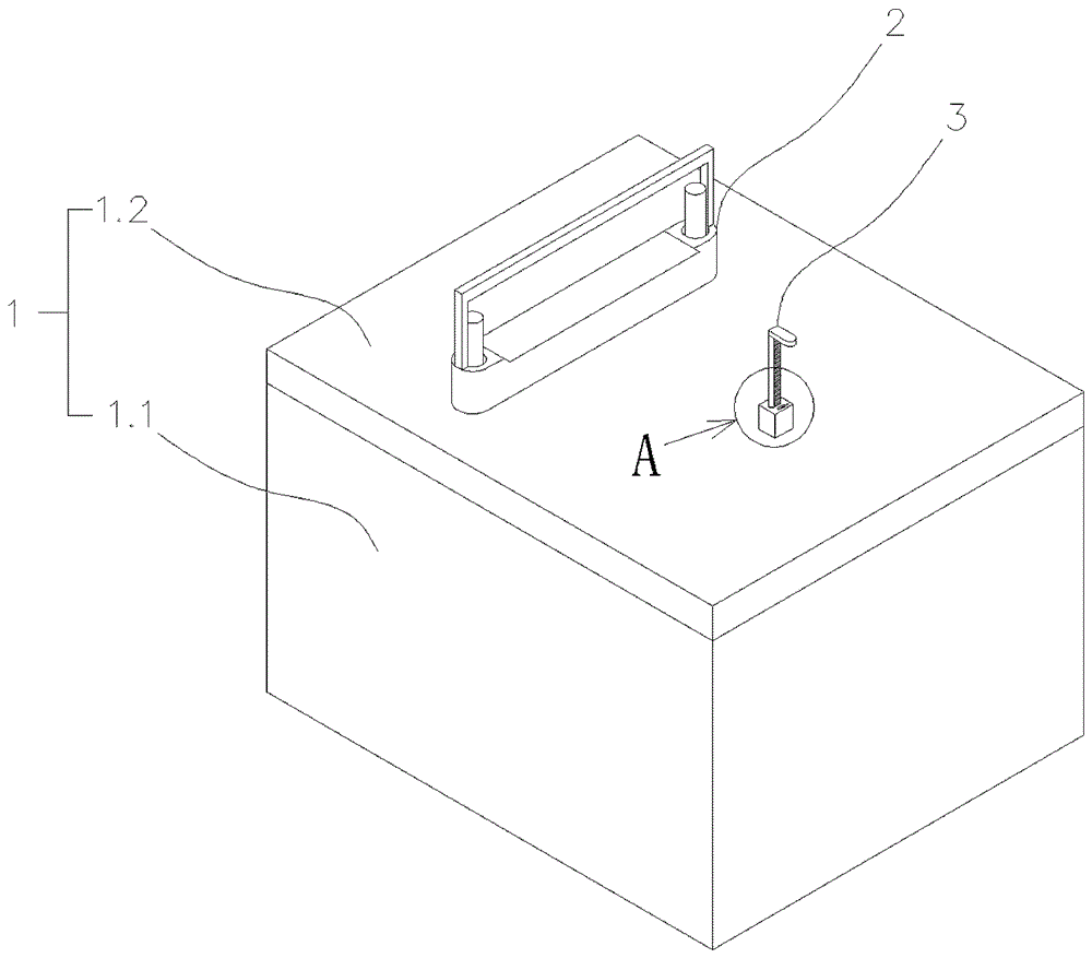
[0053] Such as Figure 1~4 As shown, the frozen sample preparation device described in this embodiment includes a housing 1, a sampling and setting out device 2, and an impact device 3. The housing 1 includes a tank body 1.1 and a cover body 1.2. The cover body 1.2 is fastened on the tank body 1.1. The stakeout device 2 and the impact device 3 are both arranged inside the housing 1; the cover body 1.2 is provided with a sampling chamber 1.2.1 and a control box 1.2.3, and the sampling chamber 1.2.1 is provided with a cover 1.2.2; The stakeout bin 1.2.1 and the control box 1.2.3 are used for the control part of the sampling device 2 and the impact device 3 respectively, and ensure the airtightness of the housing 1; Sampling and stakeout.
[0054] Such as Figure 5 As shown, the taking and setting out device 2 includes a bracket 2.1, a lifting rod 2.2, and a clamping groove 2.3. The bracket 2.1 is fixed on the bottom of the housing 1, the clamping groove 2.3 is installed on the b...
Embodiment 2
[0060] Such as Figure 9 , 10 As shown, on the basis of the above embodiments, this embodiment designs the clamping part 2.3.1 to be rotatable around the bracket 2.1, so as to cooperate with the impact of the impact device 3, buffer the impact action, and avoid other forms of damage to the sample. For this reason, the bracket 2.1 is provided with a blocking piece 2.1.1, the bracket part above the blocking piece 2.1.1 is cylindrical, and the clamping part 2.3.1 is arranged above the blocking piece 2.1.1 and can rotate around the bracket 2.1. At the same time, connecting parts 2.2.1 are also provided at both ends of the lifting rod 2.2, and the clamping part 2.3.1 has a connecting groove 2.3.3. part 2.3; in addition, in order to make the clamping part 2.3.1 return to the original position after being impacted and rotated, a return spring 2.3.4 can be set in the connection groove 2.3.3, and the return spring 2.3.4 can be With the limit block 2.3.5 as the support point, the clam...
Embodiment 3
[0062] Such as Figure 11 , 12 As shown, on the basis of the above embodiments, the stroke of the impact spring 3.4 in this embodiment can be adjusted to control its impact strength and position, and the stroke adjustment is realized by the adjustment structure 3.5 arranged on the strut 3.2. The adjustment structure 3.5 has multiple implementation forms, the following are two typical forms.
[0063] The first type: the adjustment structure 3.5 is a slideway 3.5.1, the slideway 3.5.1 is fixed on the cover body 1.2, the top of the pole 3.2 is connected to the slideway 3.5.1, and the pole 3.2 can be placed on the slideway 3.5. 1 slides upward; one end of the slideway 3.5.1 is provided with a knob 3.5.2, and the knob 3.5.2 is connected to the pole 3.2 through a gear-link transmission mechanism (the gear-link transmission technology is common, not shown in the figure), and rotates Knob 3.5.2 can make strut 3.2 shift on slideway 3.5.1, thereby can adjust the impact intensity of la...
PUM
 Abstract
Description
Claims
Application Information
 - R&D
- Intellectual Property
- Life Sciences
- Materials
- Tech Scout
- Unparalleled Data Quality
- Higher Quality Content
- 60% Fewer Hallucinations
Browse by: Latest US Patents, China's latest patents, Technical Efficacy Thesaurus, Application Domain, Technology Topic, Popular Technical Reports.
© 2025 PatSnap. All rights reserved.Legal|Privacy policy|Modern Slavery Act Transparency Statement|Sitemap|About US| Contact US: help@patsnap.com


