
Robot gripper and method for its manufacture

a robot and gripper technology, applied in the field of robot grippers, can solve the problems of insufficient assembly quality of assembled components and assembly itself, the quality of the assembled components is too low, and the manufacturing process requires both cost-intensive assembly and reliable quality control

Inactive Publication Date: 2011-09-06
FRAUNHOFER GESELLSCHAFT ZUR FOERDERUNG DER ANGEWANDTEN FORSCHUNG EV
View PDF10 Cites 25 Cited by
  • Summary
  • Abstract
  • Description
  • Claims
  • Application Information

AI Technical Summary

Benefits of technology

This approach significantly reduces production costs and time, enabling grippers to be tailored to specific tasks with improved performance and service lifetime, and allows for automated production and adaptation to various sizes and shapes, enhancing their use with dynamic robot arms.

Problems solved by technology

Industry-standard grippers are subject however to a certain amount of wear to seals, bearings and guides, which is the dominant factor particularly in those cases in which the quality of the assembled components and that of the assembly itself is too low.
Consequently their manufacture requires both cost-intensive assembly as well as reliable quality control.
Despite the existing high quality requirements on mechanical gripper systems, which ultimately can only be satisfied by cost-intensive measures with regard to the quality of the components themselves and with regard to the assembly, for reasons based on the constraints of competition there is a requirement to keep the manufacturing costs as low as possible, which means individual sizes and customized variants for specific gripping tasks cannot be offered for the design of such grippers for reasons of cost.
Such an expense, in particular when handling small quantities, can become excessive in comparison to the overall gripper system, so that many types of gripping tasks cannot be automated due to reasons of cost.
In addition is the fact that the individual modifications to be made lead to modules that are not weight-optimized and thus adversely affect the performance of conventionally produced gripper platforms.

Method used


Image

  • Robot gripper and method for its manufacture
  • Robot gripper and method for its manufacture
  • Robot gripper and method for its manufacture

Examples


Embodiment Construction

[0012]The problem addressed by the invention is to extend a robot gripper of the type previously described with a fixing flange for detachably attaching it to a robot manipulator arm, and with at least one actuator element which is supported in a frame, that actuates at least two gripper jaws indirectly or directly kinematically via at least one articulated unit, in such a way that the manufacture of such a robot gripper is simplified, cheaper and faster in comparison to the assembly techniques used to date. It should thus be possible to manufacture a robot gripper individually adapted to a specific gripping task even in very low quantities at an economically viable cost, and this with a gripper quality which in no way compromises on the functionality or the service lifetime of the gripper system. It should thus moreover also be possible to manufacture a robot gripper to any chosen scaling, without having to accept a large outlay in terms of assembly effort and cost.

[0013]The soluti...


PUM


Abstract

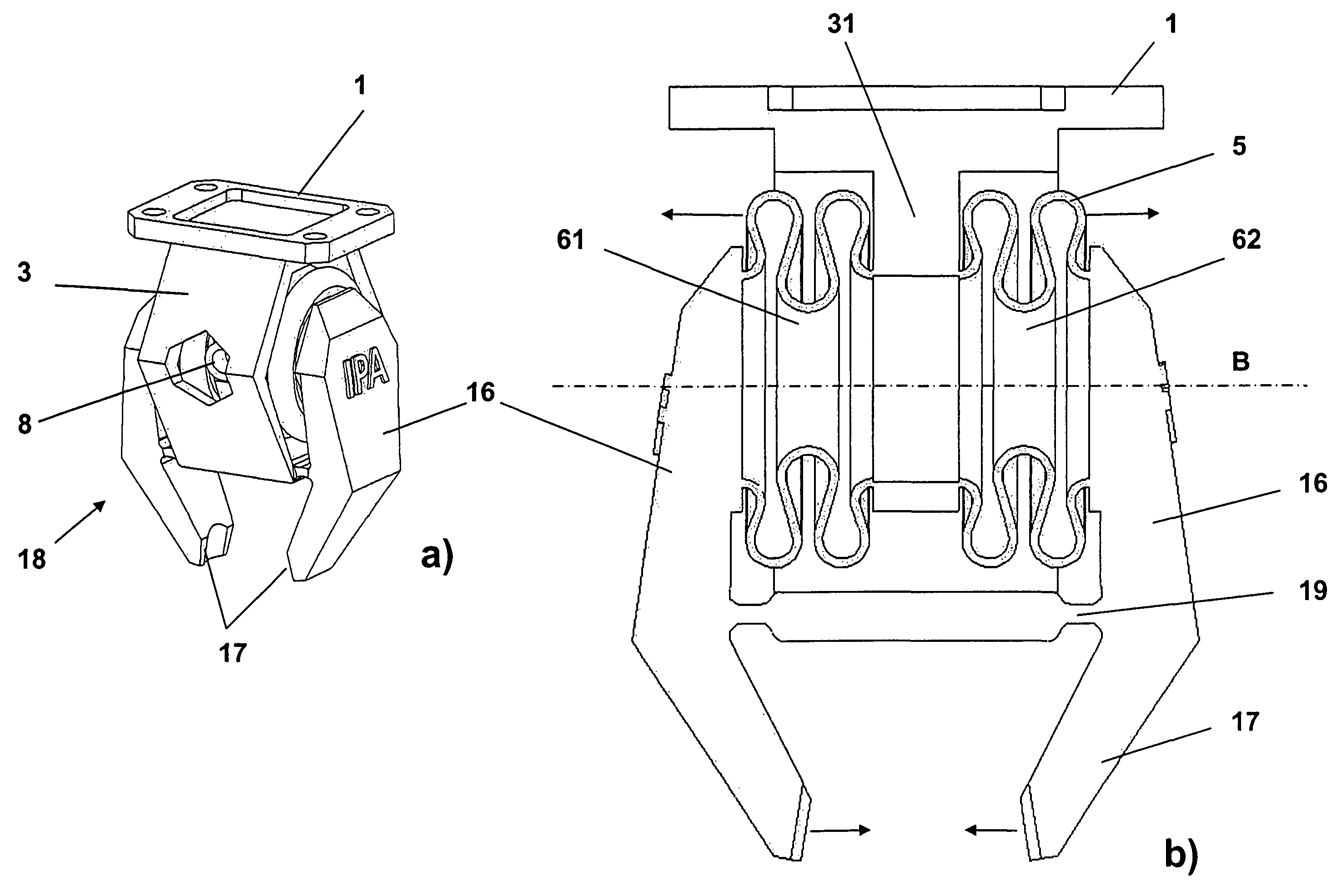
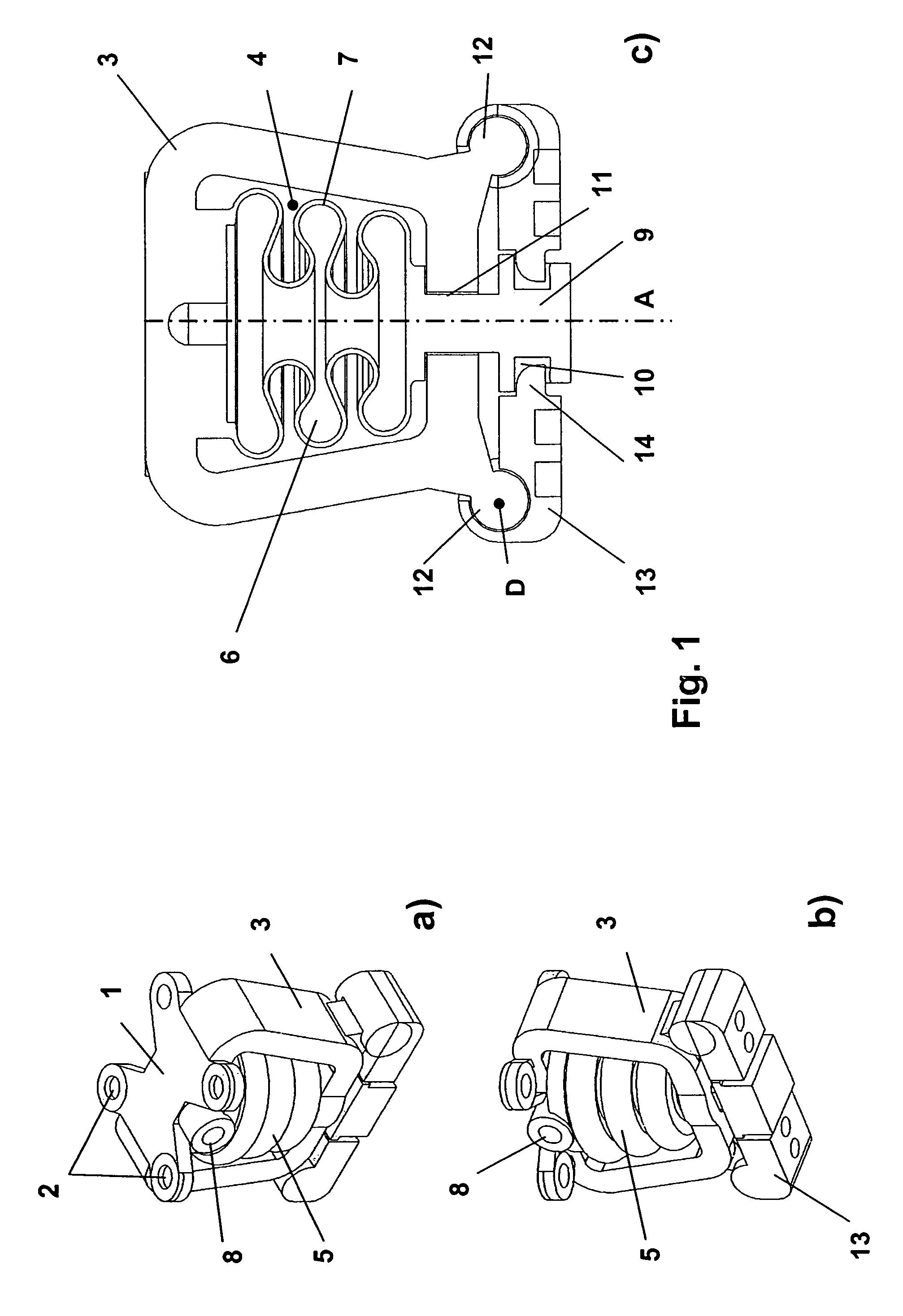
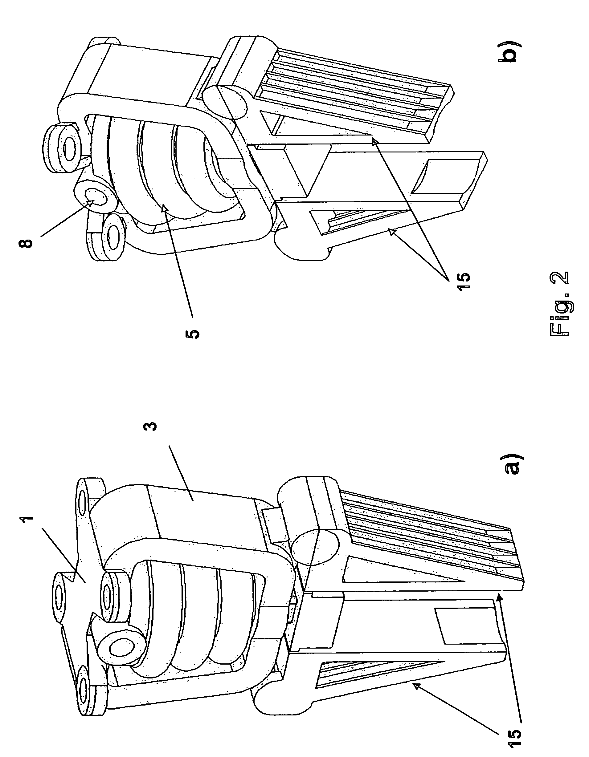
The invention relates to a robot gripper having a fixing flange for detachably attaching it to a robot manipulator arm, and at least one actuator element which is supported in a frame, that actuates at least two gripper jaws indirectly or directly kinematically via at least one articulated unit. At least the fixing flange, the frame and the actuator element are manufactured integrally using a generative manufacturing method, and the actuator element is in the form of a bellows, enclosed an internal volume, which can be filled with a medium via at least one opening, and is capable of expanding, when filled with a medium, along a linear axis predetermined by the bellows design of the actuator element and of contracting, when the volume is emptied, in the opposite direction.

Description

TECHNICAL FIELD[0001]The invention relates to a robot gripper having a fixing flange for detachably attaching it to a robot manipulator arm, and at least one actuator element which is supported in a frame, that actuates at least two gripper jaws indirectly or directly kinematically via at least one articulated unit.PRIOR ART[0002]Robot grippers are required in automated industrial handling for transporting, positioning or the manipulation of or on workpieces, which for example between individual process stages must be moved from conveying devices to machines, devices or packaging units where they are stored in a specific way. Such grippers are typically fixed to robot arms or to the end regions of linear or rotational drives, but are also used as permanently mounted clamping devices, for example for laser-labelling arbitrary components.[0003]The use of robot grippers on robots or other movable axles requires the weight of a gripper to be kept as low as possible, in order not to plac...

Claims


Application Information

Patent Timeline
Patent Type & Authority Patents(United States)
IPC IPC(8): B25J15/08
CPCB25J9/142B25J15/0226B25J15/0253B33Y80/00
Inventor BECKER, RALFGRZESIAK, ANDRZEJ
Owner FRAUNHOFER GESELLSCHAFT ZUR FOERDERUNG DER ANGEWANDTEN FORSCHUNG EV
Learn More