Transmitter with low latency technology

A transmitter, low-latency technology, applied in the direction of instruments, electrical digital data processing, etc., can solve problems that are rarely paid attention to, and achieve the effect of shortening the output delay time and transmission delay

Inactive Publication Date: 2017-06-06
CHANGSHA JEMO IC DESIGN CO LTD
View PDF5 Cites 0 Cited by
  • Summary
  • Abstract
  • Description
  • Claims
  • Application Information

AI Technical Summary

Problems solved by technology

[0006] The delay time of the second part can be shortened by using programmable current technology, and this technology is very mature, and a large number of products using this technology have been mass-produced; but for the delay time of the first part, it is rarely used notice

Method used


Image

  • Transmitter with low latency technology
  • Transmitter with low latency technology
  • Transmitter with low latency technology

Examples


Embodiment Construction

[0031] The present invention will be described in further detail below in conjunction with the accompanying drawings and specific embodiments.

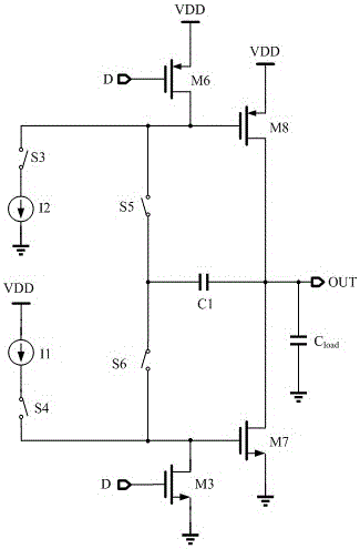
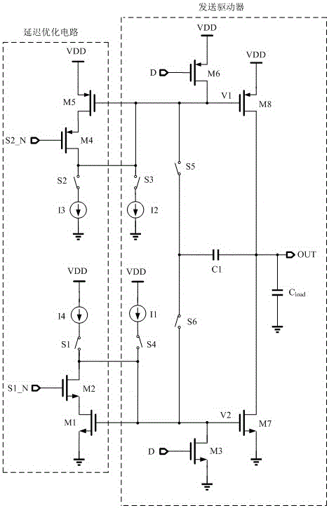
[0032] see figure 2 As shown, a transmitter using low-delay technology in the present invention mainly includes two parts: a delay optimization circuit and a transmission driver circuit.

[0033] combine figure 2 As shown, when the transmitter sends high and low levels, it mainly includes three working states: entering the edge transition state, realizing edge transition and maintaining high and low levels. The specific implementation methods are as follows:

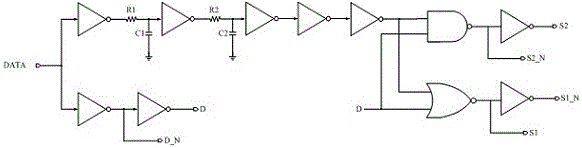
[0034] The initial state is low level, when the high level is sent, the input data jumps from low level to high level, and the switch control signal generation circuit image 3 Corresponding control signals will be generated, specifically, differential data signals D and D_N are generated by using single-ended to differential technology, and corresponding narrow pulse signal...


PUM


Abstract

The invention discloses a transmitter with low latency technology comprising a delay optimization circuit and a transmission driver. When the transmission data is subjected to a high transition, an delaying optimization circuit performs a large current discharge on a gate V1 of a driving tube M8, and realizes an quickly output entry into a high transition state, and then uses a small current to maintain a rise and the subsequent high level output state; when the transmission data starts low transition, the delay optimization circuit carries on the large current charging to a gate V2 of a driving tube M7, realizes the output to enter into a low transition state, and then uses the small current to keep a down and the subsequent low level output state; at the same time, utilizing negative feedback capacitor technology, and outputting ripple with a better suppression. The transmitter with low latency technology has the advantages of being fast input in transition response, short in output delay; low in outputting ripple, and suitable for the field of integrated circuit transceiver chip design.

Description

technical field [0001] The present invention mainly relates to the design field of analog integrated circuit transceivers, specifically a transmitter using low-delay technology. Transition state, using small current technology to realize output edge transition and maintain the corresponding output state, which greatly shortens the transmission delay time of the transmitter. Background technique [0002] As a key module of the wired data communication interface chip, the transmitter mainly performs data transmission between devices and realizes data communication between master and slave devices. With the increasing amount of communication data, the requirements for the transmitter's operating rate are getting higher and higher, and the requirements for transmission delay are becoming more and more stringent. The quality of its design will directly affect the signal transmission volume and response rate between devices. Therefore, more and more researchers study and verify t...

Claims


Application Information

Patent Timeline
Patent Type & Authority Applications(China)
IPC IPC(8): G06F13/40
CPCG06F13/4077
Inventor 郭斌
Owner CHANGSHA JEMO IC DESIGN CO LTD
Why Eureka
Try Eureka