Wire aerodyne

A wire and roller mechanism technology, applied in the field of wire speeding, can solve the problems of cumbersome operation and danger, and achieve the effect of stable center of gravity and simple structure

Pending Publication Date: 2022-03-25
STATE GRID SHANDONG ELECTRIC POWER CO SHOUGUANG POWER SUPPLY CO +1
View PDF0 Cites 0 Cited by
  • Summary
  • Abstract
  • Description
  • Claims
  • Application Information

AI Technical Summary

Problems solved by technology

[0004] The traditional wire flying car runs on the wire between two electric towers, and the two ends of the wire are equipped with anti-vibration hammers. The existence of the anti-vibration hammer is an obstacle that cannot be smoothly overcome for the roller mechanism of the wire flying car; in actual work, it is necessary to The staff get off the car and climb up the wire, carry the wire flying car through the anti-vibration hammer, and then climb from the wire to the wire flying car. Not only is the operation cumbersome, but also it is located at a certain height from the ground, which is very dangerous

Method used


Image

  • Wire aerodyne
  • Wire aerodyne
  • Wire aerodyne

Examples


Embodiment 1

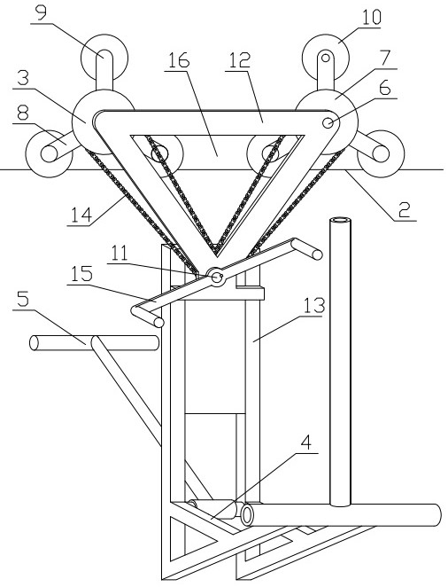
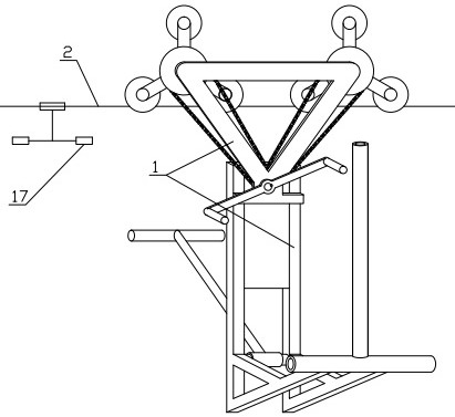
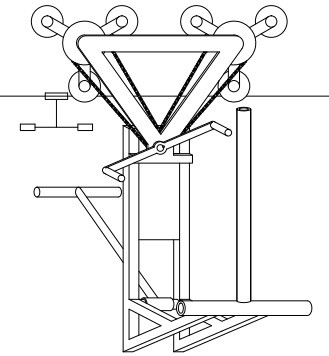
[0035] Such as Figure 1-7 As shown, the purpose of this embodiment is to provide a wire flying car, including at least two sets of roller mechanisms 3 connected to the top of the bracket 1. The bracket 1 includes an upper frame 12 and a lower frame 13. The upper frame 12 is an inverted triangle, and the two bottom corners are respectively connected. The roller mechanism 3, the top angle is connected to the conveyor belt 14 by driving the tower wheel, and the conveyor belt 14 is connected with the roller mechanism 3; The group of roller mechanisms 3 moves synchronously along the direction of the wire, so that the roller mechanism 3 swings along the direction of the wire with the axis of one group of rollers 10 as the center of a circle to achieve obstacle surmounting.

[0036] specific:

[0037] In this embodiment, the "front" guides the line flying car along the forward direction of the guide wire movement, and the "rear" guides the line flying car along the retreating direc...


PUM


Abstract

The invention relates to a lead coaster which comprises at least two groups of roller mechanisms connected to the top of a support, the support comprises an upper frame and a lower frame, the upper frame is in an inverted triangle shape, two base angles of the upper frame are connected with the roller mechanisms respectively, and top angles of the upper frame are connected with a conveying belt through driving cone pulleys. The roller mechanism comprises at least three groups of rollers which are uniformly arranged along the circumferential direction of the upper wheel; and the cone pulley is driven to rotate to drive the two groups of roller mechanisms to synchronously move along the wire direction through the conveying belt, so that the roller mechanisms swing along the wire direction by taking the axis of one group of rollers as a circle center to realize obstacle crossing. The driving cone pulley on the support and the conveying belt are used for driving the two roller mechanisms to move synchronously, and the two roller mechanisms are driven to swing towards the moving direction of the wire galloping trolley to climb over the obstacle in cooperation with rotation of rollers, close to the obstacle, in the roller mechanisms.

Description

technical field [0001] The invention relates to the field of electric facility maintenance, in particular to a wire flying car. Background technique [0002] The statements in this section merely provide background information related to the present invention and do not necessarily constitute prior art. [0003] The wire flying car is a commonly used inspection tool in the electric power inspection department. It is mainly used to assist in the power outage inspection of high-voltage lines. The traditional wire flying car uses the roller mechanism to hang the wire flying car body on the wire. The staff sits on the seat of the wire flying car body, and the ground staff uses the rope to pull the wire flying car to move it to the designated position along the guiding direction to carry out the line and Maintenance of auxiliary facilities. [0004] The traditional wire flying car runs on the wire between two electric towers, and the two ends of the wire are equipped with anti-...

Claims


Application Information

Patent Timeline
IPC IPC(8): H02G1/02
CPCH02G1/02
Inventor 郭光吉范兴龙李振东陈洪培郝强于德水张树果丁世勇李丰禄赵明亮张寿永
Owner STATE GRID SHANDONG ELECTRIC POWER CO SHOUGUANG POWER SUPPLY CO
Why Eureka
Try Eureka