
Electrolysis device for producing hydrogen through water electrolysis and method of electrolysis device

An electrolysis device, water electrolysis technology, applied in the electrolysis process, electrolysis components, cells, etc., can solve the problems of accelerated creep speed, difficulty in relaxing relaxation, increased brightness of creep deformation, etc., to reduce energy consumption and operating costs Effect

Inactive Publication Date: 2017-06-06
SHAANXI HUAQIN NEW ENERGY TECH CO LTD
View PDF6 Cites 3 Cited by
  • Summary
  • Abstract
  • Description
  • Claims
  • Application Information

AI Technical Summary

Problems solved by technology

[0006] (2) During the service process of the flat rubber seal in the compressed state, compression creep and shrinkage deformation will occur. The greater the compression force, the creep deformation will become brighter and the creep speed will increase. It is often used to increase the number of disc springs It is difficult to feed and relax

Method used


Image

  • Electrolysis device for producing hydrogen through water electrolysis and method of electrolysis device

Examples


Embodiment 1

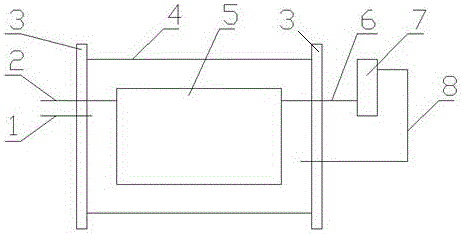
[0027] In order to overcome the problem of insufficient sealing technology of the existing medium-pressure water electrolysis hydrogen production electrolyzer, this embodiment provides a method such as figure 1 The shown water electrolysis hydrogen production electrolysis device includes an electrolysis cell 5, the outside of the electrolysis cell 5 is covered with a cylinder 4, an oxygen outlet pipe 1 is arranged in the cavity between the cylinder 4 and the electrolysis cell 5, and the electrolysis cell 5 is connected with a hydrogen outlet pipe 2.

[0028] Both ends of the cylinder 4 are respectively connected with end plates 3 , and both the oxygen outlet pipe 1 and the hydrogen outlet pipe 2 pass through the end plates 3 and are connected to the outside of the cylinder 4 .

[0029] The outside of the cylinder 4 is provided with a steam-water separator 7, and the steam-water separator 7 is connected with an oxygen balance tube 1 6 and an oxygen balance tube 2 8, and the oxy...

Embodiment 2

[0036] On the basis of embodiment 1, this embodiment provides a kind of figure 1 In the water electrolysis hydrogen production electrolysis device shown, the cylinder 4 adopts a cylindrical structure formed by integral welding, the electrolytic cell is placed inside the sealed cylinder, and the two ends of the cylinder are sealed with end plates to form only two sealing surfaces. It solves the problem of many sealing surfaces and poor sealing effect of crude oil equipment. Since the strength of the sealed end plate is high, the end plate 3 is made of high-strength carbon steel plate, and the strength of the end plate 3 is determined according to the design pressure.

[0037] Both ends of the cylinder 4 are welded with flanges, and the flanges are sealed with the end plate 3, which can be completed by traditional flange sealing, and the sealing effect can reach more than 10 MPa.

[0038]In order to further increase the sealing effect, gaskets are provided between the flanges a...


PUM

PropertyMeasurementUnit
pressureaaaaaaaaaa

Abstract

The invention provides an electrolysis device for producing hydrogen through water electrolysis and a method of the electrolysis device. The electrolysis device comprises an electrolytic tank, wherein a cylinder is arranged outside the electrolytic tank in a sleeving manner; an oxygen discharging pipe is arranged in a cavity between the cylinder and the electrolytic tank; the electrolytic tank is connected with a hydrogen discharging pipe; hydrogen produced from the electrolytic tank is discharged through the hydrogen discharging pipe and directly enters a use workshop; oxygen produced from the electrolytic tank enters a steam-water separator through an oxygen balance pipe I, so as to remove steams and water from the oxygen; the water-removed oxygen enters the cavity between the cylinder and the electrolytic tank through an oxygen balance pipe II; finally, the oxygen is discharged through the oxygen discharging pipe. The electrolysis device for producing the hydrogen through the water electrolysis solves the problem of defects of a sealing technology of the existing electrolytic tank for producing the hydrogen through the water electrolysis through a self-balance structure and a mode of taking the oxygen as balance gas.

Description

technical field [0001] The invention relates to water electrolysis hydrogen production equipment, in particular to an electrolysis device and method for water electrolysis hydrogen production. Background technique [0002] As we all know, increasing the working pressure of water electrolysis hydrogen production process is one of the more economical and effective ways to improve electrolysis efficiency. The working pressure of the traditional water electrolysis hydrogen production water electrolyzer is generally between 0.1MPa and 1.6MPa. In order to improve the electrolysis efficiency, in the water electrolysis hydrogen production industry at home and abroad, some increase the working pressure by 3.0MPa to 3.5MPa. It will exceed 3.5MPa, and the safety contradiction of the sealing of electrolyzers operating at high pressure higher than 3.5MPa will be further highlighted, becoming a restrictive bottleneck technology. [0003] Due to the low volume energy density of hydrogen, ...

Claims


Application Information

Patent Timeline
Patent Type & Authority Applications(China)
IPC IPC(8): C25B1/12C25B9/00
CPCC25B1/04C25B9/00C25B9/05Y02E60/36
Inventor 王彦东何兴用杨炎成博
Owner SHAANXI HUAQIN NEW ENERGY TECH CO LTD
Learn More