
Boosted cleaning mop

A mop and cleaning technology, applied in cleaning equipment, cleaning machinery, vehicle exterior cleaning devices, etc., can solve the problems of mopping effort, loss, and poor effect

Pending Publication Date: 2017-06-06
常涛涛
View PDF8 Cites 15 Cited by
  • Summary
  • Abstract
  • Description
  • Claims
  • Application Information

AI Technical Summary

Problems solved by technology

Its advantage is that it is convenient and easy to use, does not need water, and can be used repeatedly for a long time; the disadvantage is that it is purely manual, dragging and wiping is laborious, and the cleaning effect is limited
There is also an obvious defect: when the dust attached to the oil mop is cleaned after wiping the car, it can only be shaken off or beaten mechanically, which will cause obvious dust pollution, and it is not easy to clean thoroughly. , the dust attached to the head of the oil mop that cannot be cleaned is increasing, so that it causes the "hardening" or "hardening" of the mop beard, which reduces or even loses the adhesion, resulting in the failure or scrapping of the oil mop. One defect caused the effect of oil mop to carry out car cleaning continued to deteriorate and weaken, and the life of the mop was generally short
[0015] In the process of understanding the various types of mops and their improvement and development process, we can find and summarize two problems: one is the dehydration of the mop head after washing, which is related to the ease of use and cleaning effect of the mop, and the other is However, almost all mops are purely manual or purely artificial. Even if the rotary mop has taken measures to improve the cleaning and dehydration methods, and even added a power device to the mop bucket, it has not touched the mopping process. The most time-consuming and labor-intensive, and the most critical part of mop use, is the problem of increasing power assistance

Method used


Image

  • Boosted cleaning mop
  • Boosted cleaning mop
  • Boosted cleaning mop

Examples


Embodiment Construction

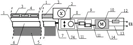
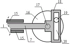
[0055] figure 1 It is a side view partial structural schematic diagram of embodiment 1, figure 2 Yes figure 1 Schematic diagram of the side-view partial detail structure of the "rotational to linear reciprocating motion conversion device" in figure 1 and figure 2 The partial structure schematic diagram of composition embodiment 1. The partial schematic line 1 is intercepted to indicate that it is only a display of local structural features in the figure. The mop whiskers 5 are rooted and supported on the mop whisker planting body 6, and the two are combined to form a brush-like mop head, which is connected to the mop through the telescopic rod 7. The motion conversion device 8 that turns into a straight line and reciprocates is connected to the motor 10 through the gear transmission 9 and the transmission shaft 11, and the input power Ui is connected to the motor 10 through the circuit switch 12 and the wire 13. Vacuum cleaner intake pipe 3 is columnar or flat strip, is ...


PUM


Abstract

The invention relates to a boosted cleaning mop and belongs to the field of sanitation and cleaning. An optimal scheme that moping and wiping auxiliary power is put on a mop head is adopted in order to solve the problems that the existing mop is time consuming and labor consuming due to pure manual moping and wiping, and cleaning effect is poor due to single mop head motion forms. The boosted cleaning mop at least comprises a mop head and a handle bearing a complete mop machine, the mop head at least comprises mop strips and a planting and bearing body thereof, and the mop strips attach to the to-be-cleaned surface manually or under the force of dragging of the carrier to mop and clean the to-be-cleaned surface. The boosted cleaning mop is characterized in that a power channel is added to the mop and is used for providing auxiliary power from or formed on the mop to the mop head besides the handle drives the complete mop machine to move, the mop strips in mopping and cleaning follow the complete mop machine to move as well as is driven by the power channel synchronously, motion superposition is formed, cleaning efficiency of the mop is enhanced, labor and water are saved, the mop is sturdy and durable, and the mop is an ideal upgrade product for motor-vehicle outer surface cleaning, indoor floor and table surface cleaning mops.

Description

technical field [0001] The invention belongs to the field of hygienic cleaning and cleaning, and relates to a surface cleaning and cleaning tool, in particular to a power-assisted cleaning mop suitable for cleaning the outer surface of motor vehicles and cleaning indoor floors and countertops. It has a mop head driven by a power device and can dry Use, oil immersion and water washing, used to replace the traditional oil mop for car cleaning and indoor cleaning mop, can significantly improve the work efficiency and effect level of surface cleaning and cleaning, fast and labor-saving, thorough cleaning, water saving and environmental protection, has broad application prospects . Background technique [0002] There are usually three ways to remove dust and debris attached or accumulated on the surface of objects: one is dry cleaning, such as cleaning with a broom, blowing with a hair dryer, sucking with a vacuum cleaner, wiping with a dry rag, etc.; the other is washing with wa...

Claims


Application Information

Patent Timeline
Patent Type & Authority Applications(China)
IPC IPC(8): A47L11/283B60S3/04A47L11/40
CPCA47L11/283A47L11/40A47L11/4063B60S3/04
Inventor 常涛涛
Owner 常涛涛
Learn More