Laser energy transmission photoelectric conversion efficiency improvement method based on photocell array circuit optimization

A photoelectric cell and circuit technology, applied in the field of laser applications, can solve the problems of not being too thin, setting the laser power with a small proportion of the total area, increasing the target weight and volume of energy transmission, etc., to meet the requirements of reduction, reduce energy waste, increase The effect of large coverage

Inactive Publication Date: 2017-05-31
PLA PEOPLES LIBERATION ARMY OF CHINA STRATEGIC SUPPORT FORCE AEROSPACE ENG UNIV
View PDF10 Cites 4 Cited by
  • Summary
  • Abstract
  • Description
  • Claims
  • Application Information

AI Technical Summary

Problems solved by technology

Although the conversion efficiency is relatively low, it is mainly caused by the small ratio of the area of ​​the photovoltaic panel to the total area and the unreasonable influence of the laser power setting. In theory, the conversion efficiency can exceed 60% (UgurOrtabasi, Herbert Friedman. Powersphere: APhotovoltaic Cavity Converter for Wireless Power Transmission Using HighPower Lasers[C].Conference Record of the 2006IEEE 4th World Conference on Photovoltaic Energy Conversion,Waikoloa.Hi,USA,2006:1-4.);
[0007] Although the above several synergistic methods have improved the photoelectric conversion efficiency to a certain extent, the photoelectric cell material is limited by the spectral characteristics and cannot break through the limit of their photoelectric conversion efficiency. It is necessary to study more efficient new semiconductor materials; In this case, the thickness should not be too thin, and the operating space for the optimized structure is small; the improvement of the receiving device makes the structure of the laser receiving end more complicated, and increases the weight and volume of the energy transmission target. Need to further consider its economy and practicality

Method used


Image

  • Laser energy transmission photoelectric conversion efficiency improvement method based on photocell array circuit optimization
  • Laser energy transmission photoelectric conversion efficiency improvement method based on photocell array circuit optimization

Examples


Embodiment Construction

[0015] In conjunction with the accompanying drawings, a further detailed description will be given of the photoelectric conversion efficiency enhancement method of laser power transmission based on photovoltaic array circuit optimization of the present invention.

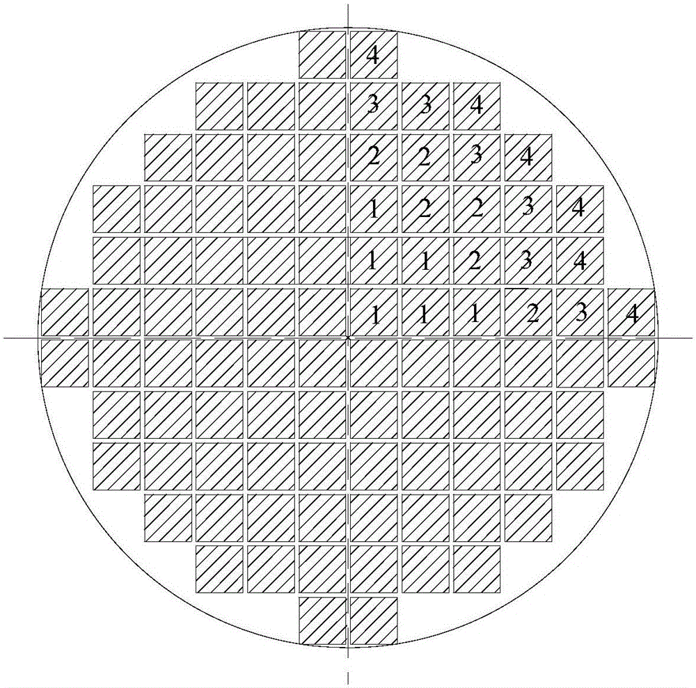
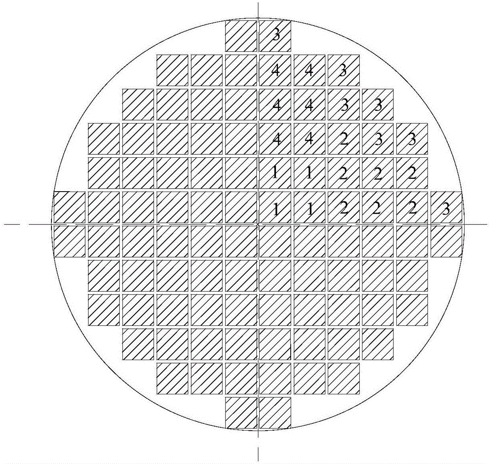
[0016] The laser spot energy targeted by the present invention is axisymmetrically distributed, and the laser irradiation power received by the photocell arrays in the four quadrants is exactly the same, and the output characteristics are also the same. Therefore, only the photocell arrays in the first quadrant are marked and explained. The remaining quadrants are consistent with the first quadrant. Optimizing series-parallel photocell arrays such as figure 1 As shown, the outermost circle represents the laser spot boundary, and the photocells with the same number represent the same group of photocell units. The photocell array is composed of 96 photocells in total. The size of a single photocell is 10mm×10mm, whic...


PUM


Abstract

The invention discloses a laser energy transmission photoelectric conversion efficiency improvement method and can reduce mismatch loss caused by nonuniform power density distribution of Gauss laser beams and improve laser energy transmission photoelectric conversion efficiency. According to the method, a circuit optimization photocell array is designed, a photocell array substrate employs a one-side tin-spraying universal plate, so the photocells can respectively realize series and parallel connection according to optimization requirements, and the photocells respectively employ monocrystalline silicon cells and are used for converting laser energy into electric energy. Compared with a photocell array in the prior art, the photocell array is arranged in an annular mode, the cells are connected according to the optimization circuit to make received laser irradiation power densities be generally identical, output currents of the cells are made to be similar, mismatch loss is reduced, and photoelectric conversion efficiency is improved. The method is advantaged in that simple structure, easy realization and strong practicality are realized, and photoelectric conversion efficiency during laser energy transmission is improved.

Description

technical field [0001] The invention belongs to the technical field of laser applications, and relates to a method for improving the photoelectric conversion efficiency of laser energy transmission. Background technique [0002] Since the output voltage and output current of a single photovoltaic cell are very small, it generally cannot be used as a power source alone. The photoelectric conversion device for laser energy transmission needs to combine multiple photovoltaic cells in series (to increase the output voltage) or in parallel (to increase the output current) to form a photovoltaic cell array and then output it to the outside, so that the area of ​​the photovoltaic cell array is relatively large, and the laser beam is actually Gaussian beam, its power density distribution is not uniform (the central radiation power density is high, the edge is low), so that the laser radiation power density received by each photocell in the photocell array is inconsistent, and the ou...

Claims


Application Information

Patent Timeline
IPC IPC(8): H01S3/09
CPCH01S3/09
Inventor 李小将李贝贝王志恒李志亮李明哲陈世媛贺景瑞
Owner PLA PEOPLES LIBERATION ARMY OF CHINA STRATEGIC SUPPORT FORCE AEROSPACE ENG UNIV
Why Eureka
Try Eureka