
Low dropout linear regulator using super transconductance structure

A low-dropout linear voltage regulator technology, applied in amplifiers, instruments, amplifiers with semiconductor devices/discharge tubes, etc., can solve the problem of large gate parasitic capacitance, insufficient SR current at the output end, limited maximum load current, etc. question

Inactive Publication Date: 2017-05-31
UNIV OF ELECTRONICS SCI & TECH OF CHINA
View PDF6 Cites 16 Cited by
  • Summary
  • Abstract
  • Description
  • Claims
  • Application Information

AI Technical Summary

Problems solved by technology

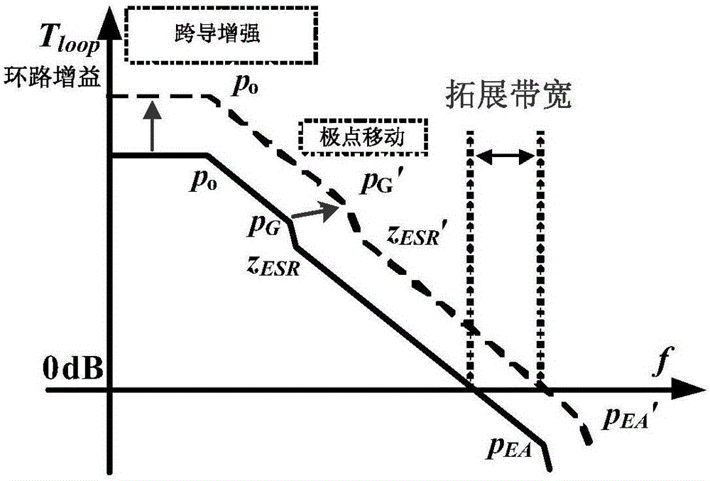
In the whole loop adjustment, the response speed of EA is limited by its unity gain bandwidth, the adjustment tube M P There is a large parasitic capacitance C on the gate PAR , so the variation of its gate voltage requires a larger EA output current I SR charge and discharge it, that is, the slew rate limit
m P The size selection needs to ensure that the maximum load current can pass through, so the general size is very large, resulting in a large gate parasitic capacitance
In this way, while introducing an ultra-low frequency pole and limiting the bandwidth of the EA, it also limits the slew rate of the EA output.
In addition, in order to achieve high gain and low power consumption, the traditional structure of the EA will select a small bias current, which will cause the output impedance of the EA to be very large, pushing the pole to the low frequency and limiting the bandwidth of the EA.
In addition, the SR current at the output terminal is insufficient, which also limits the slew rate at the output terminal.
Therefore, the transient response of the LDO on the general structure is limited by the maximum load current, loop gain (loop gain) and static power consumption

Method used


Image

  • Low dropout linear regulator using super transconductance structure
  • Low dropout linear regulator using super transconductance structure
  • Low dropout linear regulator using super transconductance structure

Examples


Embodiment Construction

[0029] The specific implementation manner and principle of the present invention will be further elaborated below in conjunction with the drawings.

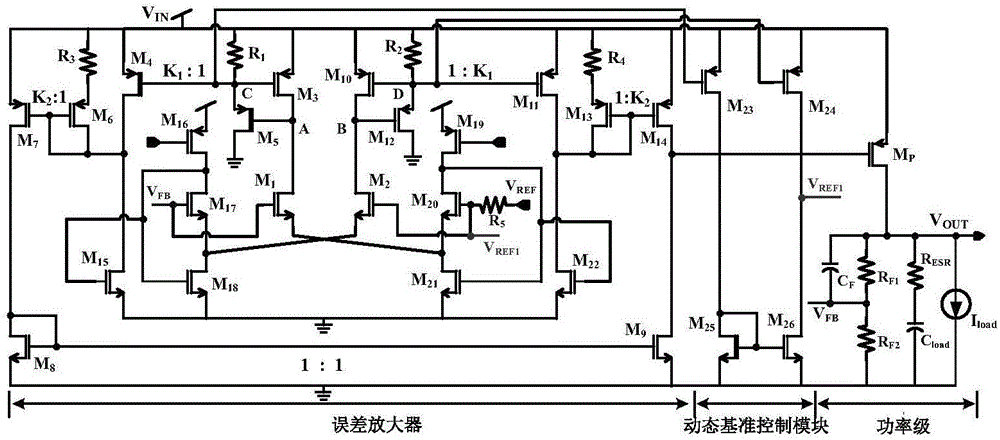
[0030] The main structure of the error amplifier EA of the present invention adopts a transconductance amplifier with a super transconductance structure, which converts a voltage signal into a current signal, and then amplifies the circuit structure with a large proportion. It is called a super transconductance structure, because only The low-frequency main pole at the output of the error amplifier EA does not introduce a new low-frequency pole, so while increasing the gain, it also expands the bandwidth.

[0031] figure 2 Shown is a complete circuit diagram of a low-dropout linear regulator using a super transconductance structure provided by the present invention, including: a resistor feedback network for generating a feedback voltage V FB , by the first feedback resistor R F1 with the second feedback resistor R F2 connect...


PUM


Abstract

The invention discloses a low dropout linear regulator using a super transconductance structure, and belongs to the technical field of power source management. The super transconductance structure, and belongs to the technical field of power source management. The super transconductance structure refers to a circuit structure that a voltage signal is transformed into a current signal, and the current signal is amplified in an extremely big proportion; an error amplifier EA adopts the super transconductance structure, differential input of the error amplifier EA feeds back a difference value between a voltage feedback VFB and a voltage dynamic reference VREF1 for a sample and transforms the difference value into a small signal current, and the small signal current is amplified by K1-fold through a first grade current mirror, and is then amplified by K2-fold through a second grade current mirror to be used for regulating the grid of a compensating pipe MP. The error amplifier EA with the super transconductance structure is adopted to widen the bandwidth of the error amplifier EA, besides, an SR current of an output end of the error amplifier EA during load transient variation is increased through a dynamic biasing technology and a dynamic reference control technology, and thus the purposes of increasing the slew rate of the error amplifier and strengthening the transient response are achieved.

Description

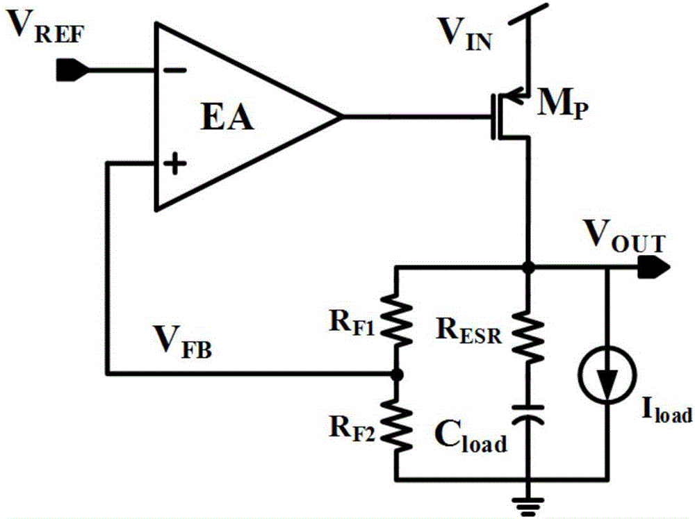
technical field [0001] The invention belongs to the technical field of power management, and in particular relates to the design of a low dropout regulator (Low Dropout Regulator, LDO). Background technique [0002] Low-dropout linear regulator (LDO) has the characteristics of low power consumption, low noise, and small chip area, and has been widely used in mobile electronic devices. [0003] A typical LDO architecture such as figure 1 As shown, it specifically includes: error amplifier EA (Error Amplifier), adjustment tube M P ,R F1 and R F2 Composed of resistor divider feedback network, the load I load , the output capacitance C load ,R ESR Represents the equivalent series resistance across the output capacitor. The basic working principle is: the resistor feedback network generates a feedback voltage through resistor division, and the error amplifier amplifies the error between the reference voltage and the feedback voltage, which is used to control the gate volta...

Claims


Application Information

Patent Timeline
Patent Type & Authority Applications(China)
IPC IPC(8): G05F3/26
CPCG05F3/262H03F3/45183H03F2200/456H03F2203/45318G05F1/575H03F2203/45288H03F3/4521
Inventor 明鑫高笛张家豪张宣魏秀凌汪尧王卓张波
Owner UNIV OF ELECTRONICS SCI & TECH OF CHINA
Learn More