Eureka AIR delivers breakthrough ideas for toughest innovation challenges, trusted by R&D personnel around the world.

Device for detecting storage battery through timing discharge under PWM (pulse width modulation) control

A detection device and storage battery technology, applied in the direction of measuring devices, measuring electricity, measuring electrical variables, etc., can solve the problems of poor continuous measurement ability, failure to meet the detection requirements of solar batteries, and inability to continuously test multiple batteries, so as to ensure accuracy Effect

Active Publication Date: 2017-05-31
大连鼎汉奇辉电子系统工程有限公司
View PDF5 Cites 1 Cited by
  • Summary
  • Abstract
  • Description
  • Claims
  • Application Information

AI Technical Summary

Problems solved by technology

[0003] 1. The battery to be tested must be fully charged. If the test object has been partially discharged, it will inevitably lead to a low measured voltage value, resulting in misjudgment;
[0004] 2. For the same battery, it cannot be measured multiple times in a short period of time. After a measurement, it takes a long time to charge before it can be measured again. The measurement efficiency is low and the accuracy is poor;
[0005] 3. The testing equipment emits a lot of heat during the testing process, so it cannot continuously test multiple batteries, and the continuous measurement capability is poor;
[0006] 4. Many links in the measurement process rely on manual work, and automatic timing and intelligent detection cannot be achieved
[0007] To sum up, the existing detection methods cannot meet the requirements of railway field solar battery detection

Method used


Image

  • Device for detecting storage battery through timing discharge under PWM (pulse width modulation) control
  • Device for detecting storage battery through timing discharge under PWM (pulse width modulation) control
  • Device for detecting storage battery through timing discharge under PWM (pulse width modulation) control

Examples


Embodiment Construction

[0026] The specific content of the present invention will be described in detail below in conjunction with the accompanying drawings.

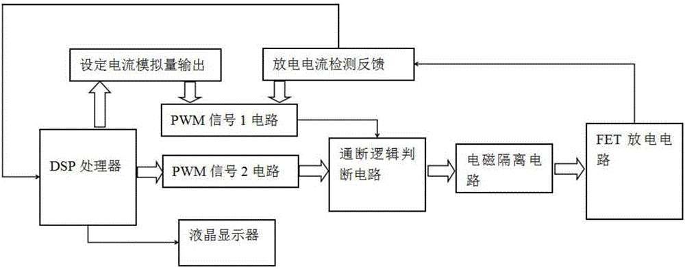
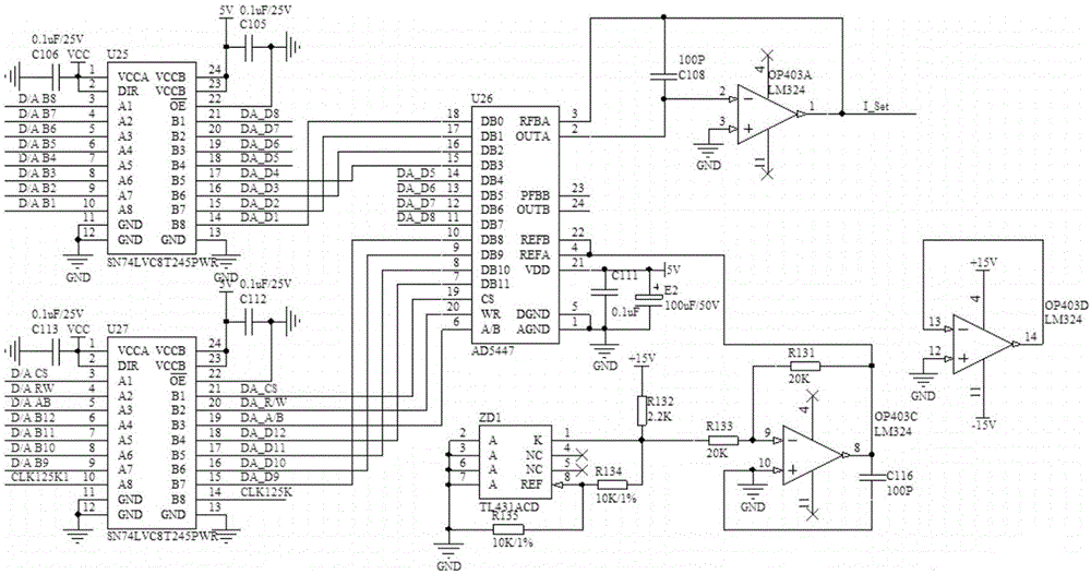
[0027] Such as figure 1 As shown, the working principle of the present invention is as follows: use the DSP28335 chip as the central processing unit, send two kinds of PWM signals, 125KHz and 2MHz, with the unique high-precision PWM output port of the chip, and the PWM signal of 2MHz is sent to the on-off signal circuit through the PWM high-frequency signal circuit. Logic judgment circuit. The DSP28335 chip encodes the discharge current value that needs to be set in the form of multi-channel digital IO output, and outputs the analog quantity to the PWM low-frequency signal circuit in the form of digital-to-analog conversion by setting the current analog quantity output circuit. At the same time, the PWM low-frequency signal circuit Receive the discharge current analog signal fed back by the discharge current detection feedback circuit, compar...


PUM


Abstract

The invention discloses a device for detecting a storage battery through timing discharge under PWM (pulse width modulation) control. The device comprises a DSP (digital signal processor), a PWM high-frequency signal circuit, a PWM low-frequency signal circuit, an on-off logic judgment circuit, an electromagnetic isolation circuit, an FET (field effect transistor) discharge circuit, a set current analog output circuit and a discharge current detection feedback circuit. According to the device, the DSP is utilized to emit high-precision PWM signals, meanwhile, fast on-off of multiple groups of FETs are controlled, so that the storage battery realizes output of constant current close to short circuit current instantaneously, and the performance condition of the storage battery is judged through rapid detection for a current peak and attenuation change by the DSP. The device can detect the storage battery at any stage in the life cycle, and with the adoption of the DSP, PWM control signal precision and current detection precision both guarantee accuracy of a detection result and universality of a detection range. Due to extreme short conduction time, little heat is generated, and repeated continuous detection can be realized.

Description

technical field [0001] The invention relates to a solar storage battery in the railway industry, in particular to a detection device for a storage battery with PWM-controlled timing discharge. Background technique [0002] At present, the method that is widely used in the railway industry to judge whether the battery is good or bad is to use a traditional discharge instrument to discharge the battery, and at room temperature to measure the attenuation value of the battery voltage at a value less than the rated cold starting current value after a long period of discharge to calculate the battery voltage. The current actual capacity, so as to determine the quality of the battery. This traditional detection method has the following disadvantages: [0003] 1. The battery to be tested must be fully charged. If the test object has been partially discharged, it will inevitably lead to a low measured voltage value, resulting in misjudgment; [0004] 2. For the same battery, it can...

Claims


Application Information

Patent Timeline
IPC IPC(8): G01R31/36
Inventor 徐起力张蔚常明
Owner 大连鼎汉奇辉电子系统工程有限公司
Why Eureka
Eureka Blog
Learn More