
Liquid chromatograph temperature control device and dehumidifying method

A liquid chromatograph and temperature control equipment technology, which is applied in the liquid chromatograph temperature control equipment and moisture removal field, can solve the problems of increasing the cost of the instrument, affecting the appearance, complex processing technology, etc., to achieve the effect of enhancing refrigeration and improving the appearance degree, the effect of low material cost

Pending Publication Date: 2017-05-31
ZHEJIANG FULI ANALYTICAL INSTR
View PDF6 Cites 0 Cited by
  • Summary
  • Abstract
  • Description
  • Claims
  • Application Information

AI Technical Summary

Problems solved by technology

The existence of condensed water will lead to uneven humidity distribution in the entire constant temperature chamber, affecting the cooling effect, and even frosting, and there will be safety hazards such as circuit board short circuit
[0004] The existing solution is to lead the condensed water to the outside of the device through a drain line to solve this problem, but this solution has some disadvantages: first, it needs to open an opening in the chassis shell for the installation of the drain line, which will The air inside the constant temperature chamber is poorly sealed, which affects the cooling effect; second, only when there is a lot of condensed water can it flow into the drain pipe, a large amount of condensed water flows in the equipment, the humidity in the equipment is high, and the cooling effect is reduced; third , internal devices such as drainage tanks are required, and the processing technology is complicated; fourth, the waste liquid tube and waste liquid bottle are added, which not only affects the appearance but also increases the cost of the instrument

Method used


Image

  • Liquid chromatograph temperature control device and dehumidifying method
  • Liquid chromatograph temperature control device and dehumidifying method
  • Liquid chromatograph temperature control device and dehumidifying method

Examples


Embodiment Construction

[0030] The following are specific embodiments of the present invention and in conjunction with the attached Figure 1-5 , The technical scheme of the present invention is further described, but the present invention is not limited to these embodiments.

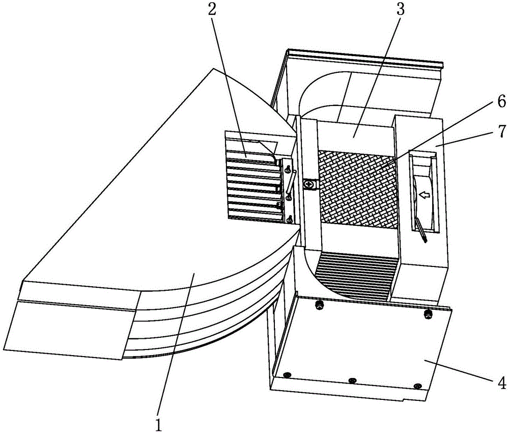
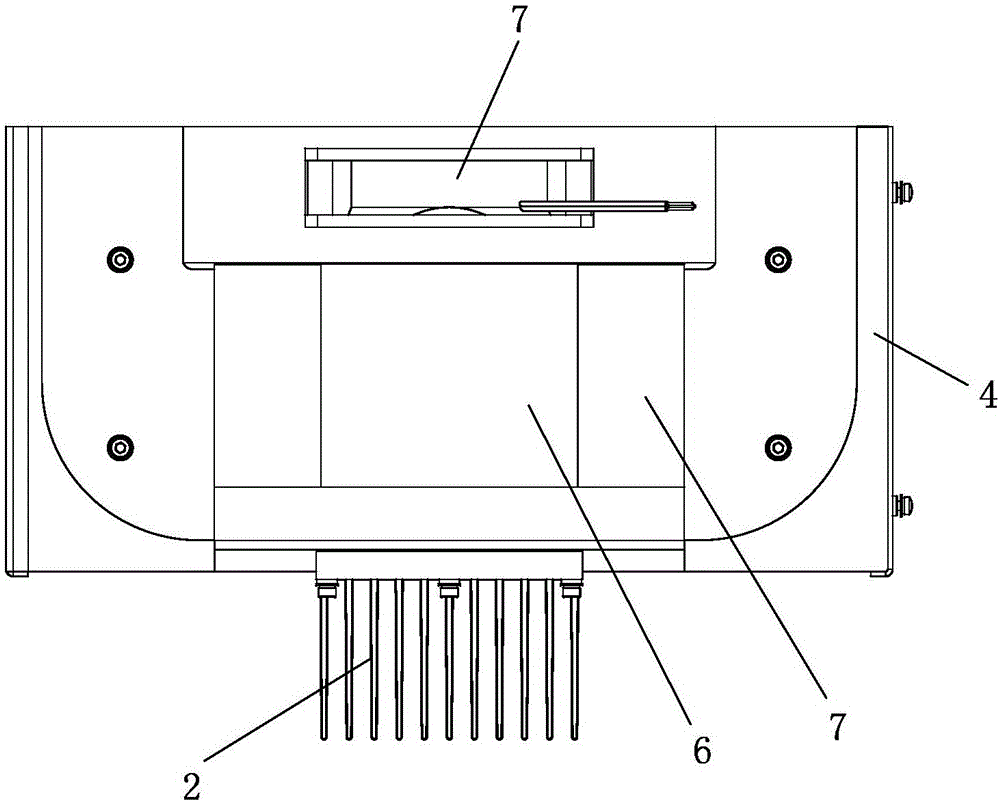
[0031] A liquid chromatograph temperature control device, comprising a constant temperature chamber 1, a cooling body 2 and a cooling block 3, the cooling body 2 and cooling block 3 are fixed on a support seat 4, and a semiconductor cooling sheet 5 is connected to the cooling body 2 and the heat dissipation block. Block 3, the cooling body 2 is placed in the constant temperature chamber 1, and the constant temperature chamber 1 is in a sealed state, and the cooling body 2 and the cooling block 3 are wrapped with water-absorbing materials 6 .

[0032] Specifically, the semiconductor cooling sheet 5 is pasted between the cooling body 2 and the heat dissipation block 3 .

[0033] More specifically, the cold end of the semiconduc...


PUM


Abstract

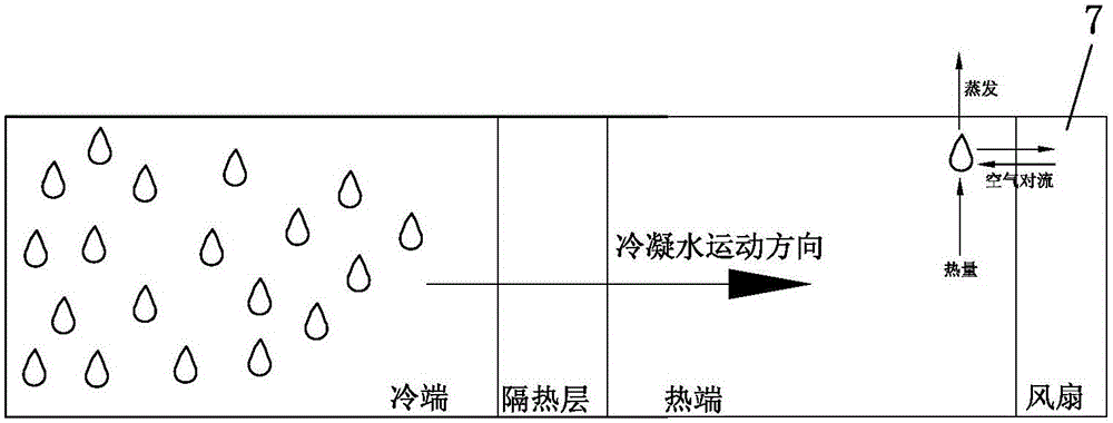
The invention belongs to the technical field of chromatographs, relates to a liquid chromatograph temperature control device and a dehumidifying method, and solves the technical problems of poor constant-temperature chamber tightness, poor refrigerating effects and complicated technology of an existing chromatograph in the dehumidifying process. The liquid chromatograph temperature control device comprises a constant-temperature chamber, a refrigerating body and a radiating block, the refrigerating body and the radiating block are fixed onto a supporting seat, a semiconductor refrigerating chip is connected with the refrigerating body and the radiating block, the refrigerating body is placed in the constant-temperature chamber in a sealed state, and water absorbing materials wrap the refrigerating body and the radiating block. By the aid of the principle of capillary action, condensed water in the constant-temperature chamber is transferred to the outside of the constant-temperature chamber by the water absorbing materials, the tightness and the refrigerating effects of the constant-temperature chamber are completely not affected, flow guide channel drainage pipes are omitted, attractiveness of the whole device is improved, the device is blow-dried by a radiator fan, and the refrigerating effects are remarkably enhanced during dehumidifying.

Description

technical field [0001] The invention belongs to the technical field of chromatography, and relates to a liquid chromatography temperature control device and a moisture removal method. Background technique [0002] Chromatography is an efficient separation and analysis technology, which can quickly separate different components in various samples, and then perform qualitative and quantitative analysis one by one. The development of modern technology and industry has promoted the rapid development and popularization of chromatographic instruments, and various newer and more applicable chromatographic techniques and chromatographic instruments are constantly emerging. With the wide application of chromatography in the fields of science and technology, such as life science, bioengineering, environmental science and ecological protection, modern medicine and traditional Chinese medicine, the requirements for chromatographic analysis conditions are getting higher and higher, such ...

Claims


Application Information

Patent Timeline
Patent Type & Authority Applications(China)
IPC IPC(8): G01N30/02F25B21/02F25B47/00
CPCF25B21/02F25B47/00G01N30/02
Inventor 周小靖江仁谦徐力蒋婷婷
Owner ZHEJIANG FULI ANALYTICAL INSTR
Learn More