
Lubricating grease conveying device with little residual oil amount

A technology of conveying device and lubricating grease, which is applied in the direction of engine lubrication, engine components, mechanical equipment, etc., can solve the problems of high working pressure, unfavorable saving and environmental protection, and high labor intensity of pump source conveying vehicles, and achieve the solution of oil supply and Conveying problems, simple structure, and the effect of reducing labor intensity

Inactive Publication Date: 2017-05-31
郭广才
View PDF6 Cites 0 Cited by
  • Summary
  • Abstract
  • Description
  • Claims
  • Application Information

AI Technical Summary

Problems solved by technology

[0003] 1. In order to overcome the resistance caused by the long conveying pipeline, the working pressure of the pump source conveying vehicle is very high, which is prone to leakage and causes on-site pollution; the existing grease conveying device, when conveying the grease in a large barrel, reaches the bottom of the barrel There is still a large amount of grease remaining (about 20KG), causing a lot of waste, which is not conducive to saving and environmental protection;
[0004] 2. When replacing a large barrel of lubricating grease, the labor intensity is high, the operation is dangerous, and it is easy to cause personal injury

Method used


Image

  • Lubricating grease conveying device with little residual oil amount
  • Lubricating grease conveying device with little residual oil amount

Examples


Embodiment Construction

[0019] The technical solution of this patent will be further described in detail below in conjunction with specific embodiments.

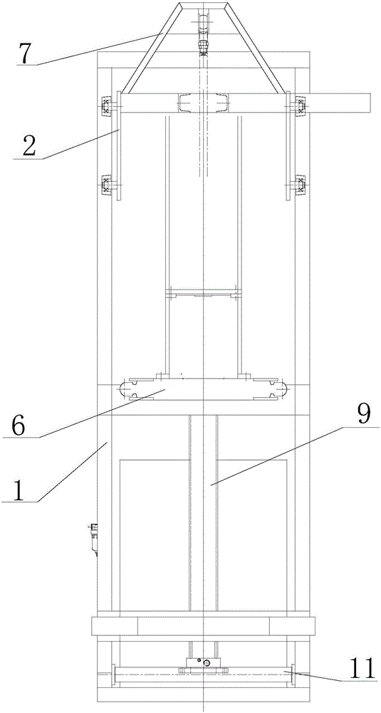
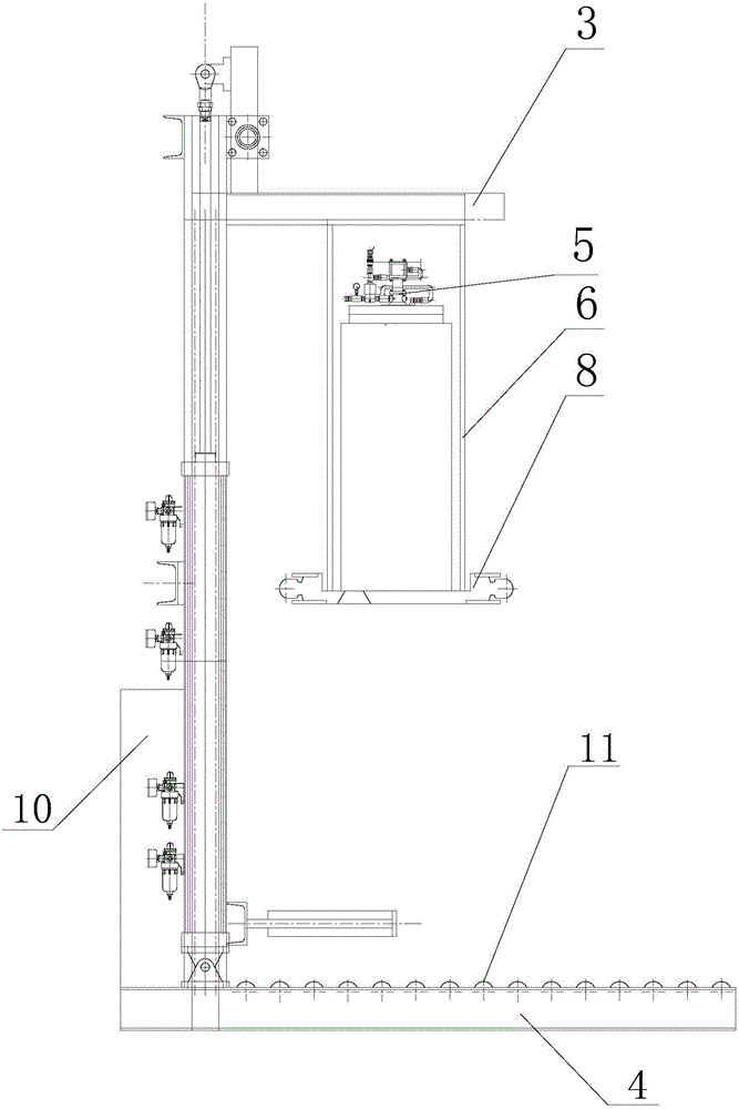
[0020] see Figure 1-2 , a lubricating grease conveying device with less residual oil, comprising a door-shaped frame 1, a pulley 2, a flange seat cylinder 9 and a high-pressure pneumatic air pump 5, a pulley 2 is arranged inside the door-shaped frame 1, and the pulley 2 is connected to a cantilever 3, the other end of the cantilever 3 is provided with a hanger 6, the bottom of the hanger 6 is equipped with an oil suction plate 8, and an oil suction nozzle is arranged on the oil suction plate 8, and one end of the oil suction nozzle is connected with the oil inlet of the high-pressure pneumatic air pump 5, The oil outlet of the high-pressure pneumatic air pump 5 is connected to one end of the oil pipe, and the other end of the oil pipe is connected to the first oil pipe joint provided on the hanger 6. The first oil pipe joint is connected to the se...


PUM


Abstract

The invention discloses a lubricating grease conveying device with little residual oil amount. The lubricating grease conveying device comprises a door-shaped frame, a sliding trolley, a flange seat air cylinder and a high-pressure pneumatic air pump, wherein the sliding trolley is arranged in the door-shaped frame; the sliding trolley is connected with one end of a suspension arm; a hanging bracket is arranged at the other end of the suspension arm; an oil sucking disc is mounted at the bottom of the hanging bracket; an oil sucking nozzle is arranged on the oil sucking disc; one end of the oil sucking nozzle is connected with an oil inlet of the high-pressure pneumatic air pump; an oil outlet of the high-pressure pneumatic air pump is connected with one end of an oil pipe; the other end of the oil pipe is connected with a first oil pipe joint arranged on the hanging bracket; the first oil pipe joint is connected with a second oil pipe joint through a hose; the second oil pipe joint is mounted on the door-shaped frame; the top of the suspension arm is connected with an air cylinder suspension beam; and the air cylinder suspension beam is connected with a piston rod of the flange seat air cylinder. According to the lubricating grease conveying device disclosed by the invention, lubricating grease of a whole barrel can be sucked out to the maximum extent, so that the cost is greatly reduced; the lubricating grease conveying device also plays a role of environmental protection; the labor strength of workers is alleviated; and danger in work is reduced, the physical safety of workers is protected, and the lubricating grease conveying device has a broad market prospect, and is worth wide popularization.

Description

technical field [0001] The invention relates to the field of grease delivery, in particular to a grease delivery device with less residual oil. Background technique [0002] At present, after the user purchases a whole barrel of grease, it is used for each lubricated part according to the production needs, and the ordinary grease pump is used to replenish oil to the high-pressure pump, which has the following defects: [0003] 1. In order to overcome the resistance caused by the long conveying pipeline, the working pressure of the pump source conveying vehicle is very high, which is prone to leakage and causes on-site pollution; the existing grease conveying device, when conveying the grease in a large barrel, reaches the bottom of the barrel There is still a large amount of grease remaining (about 20KG), causing a lot of waste, which is not conducive to saving and environmental protection; [0004] 2. When replacing a large barrel of lubricating grease, the labor intensity...

Claims


Application Information

Patent Timeline
Patent Type & Authority Applications(China)
IPC IPC(8): F16N7/38
CPCF16N7/38
Inventor 郭广才
Owner 郭广才
Learn More