Eureka AIR delivers breakthrough ideas for toughest innovation challenges, trusted by R&D personnel around the world.

Method, device and system for detecting damage of fan blades based on unmanned aerial vehicle

A technology for wind turbine blade and damage detection, applied in the field of wind power, can solve the problems of increased operation time and operation cost, low accuracy of damage location, and inability to detect automatically, so as to save operation time and cost and improve detection efficiency. Effect

Active Publication Date: 2017-05-31
BEIJING GOLDWIND SCI & CREATION WINDPOWER EQUIP CO LTD
View PDF4 Cites 36 Cited by
  • Summary
  • Abstract
  • Description
  • Claims
  • Application Information

AI Technical Summary

Problems solved by technology

[0004] However, the above method has the following disadvantages: firstly, it cannot automatically detect which position of the blade the damage appears in the photographed fan blade; secondly, since the specific position of the damage is not clear, it needs to be manually determined Damage location, the accuracy of the damage location determined manually is not high
In turn, it brings inconvenience to the follow-up fan blade maintenance work, and increases the operation time and operation cost virtually.

Method used


Image

  • Method, device and system for detecting damage of fan blades based on unmanned aerial vehicle
  • Method, device and system for detecting damage of fan blades based on unmanned aerial vehicle
  • Method, device and system for detecting damage of fan blades based on unmanned aerial vehicle

Examples


Embodiment 1

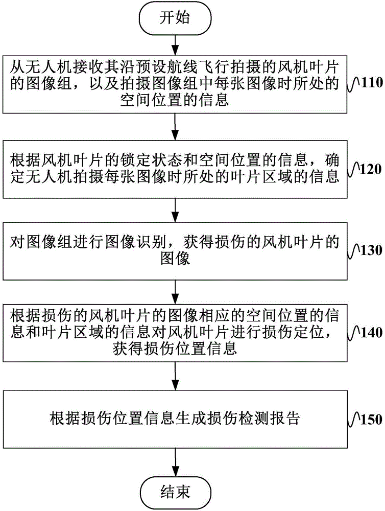
[0050] figure 1 It is a schematic flow chart of a method for detecting damage to a fan blade based on an unmanned aerial vehicle in Embodiment 1 of the present invention, as figure 1 As shown, UAV-based wind turbine blade damage detection methods include:

[0051] Step 110: Receive the image group of the fan blade taken by the UAV flying along the preset route, and the information of the spatial position where each image in the image group is taken.

[0052] In a specific implementation manner, when planning the preset route of the UAV, the preset route can be decomposed into many points in space, and each point in space has its own spatial position. Here, the information on the spatial location may include, but not limited to, longitude, latitude, and elevation. The UAV flies in the wind farm according to the preset route, and takes pictures of the fan blades in the wind farm, so that the images of the fan blades sent back by the UAV can be received in real time, and these ...

Embodiment 2

[0122] Figure 9 It is a schematic structural diagram of a UAV-based fan blade damage detection device according to Embodiment 2 of the present invention, which can be used to perform such as figure 1 The method steps of the illustrated embodiment.

[0123] refer to Figure 9 , the UAV-based wind turbine blade damage detection device includes an image and information receiving module 910 , an information determination module 920 , an image recognition module 930 , a damage location module 940 and a report generation module 950 .

[0124] The image and information receiving module 910 is used to receive the image group of the fan blade taken by the UAV flying along the preset route, and the information of the spatial position where each image in the image group was taken.

[0125] The information determining module 920 is configured to determine the information of the blade area where the UAV takes each image according to the locking state of the fan blade and the information...

Embodiment 3

[0144] An embodiment of the present invention provides a UAV-based fan blade damage detection system, including a UAV and the UAV-based fan blade damage detection device described in the second embodiment, the UAV and UAV-based The fan blade damage detection device is connected in communication.

[0145] The UAV-based fan blade damage detection system provided by the embodiment of the present invention receives the image group of the fan blade taken by the UAV along the preset route and the spatial position of each image when it is taken; according to the fan The information of the locking state and spatial position of the blade determines the information of the blade area where the UAV takes each image; further identifies the image group to obtain the image of the damaged fan blade; based on the image of the damaged fan blade, the corresponding The information of the spatial position and the information of the blade area are used to locate the damage of the fan blade and obta...


PUM


Abstract

The embodiment of the invention provides a method, device and system for detecting damage of fan blades based on an unmanned aerial vehicle. The method comprises the steps of receiving an image set of the fan blades shot from the unmanned aerial vehicle when the unmanned aerial vehicle flies along a preset airline and information of the located space position when each image in the image set is shot; determining information of the blade region where the unmanned aerial vehicle is located when the unmanned aerial vehicle shoots each image according to the locking state of the draught fan blades and the information of the space position; conducting image recognition on the image set, and obtaining the images of the damaged draught fan blades; conducting damage location on the draught fan blades according to the information of the space position and the information of the blade region which correspond to the images of the damaged draught fan blades, and obtaining damage position information; generating a damage detecting report according to the damage position information. According to the method, device and system for detecting the damage of the fan blades based on the unmanned aerial vehicle, the purpose of utilizing the unmanned aerial vehicle to automatically and accurately detect the damage of the draught fan blades is achieved, the detecting efficiency is improved, technological support is provided for follow-up blade maintenance, and the working hours and cost are saved.

Description

technical field [0001] The invention relates to the technical field of wind power, in particular to a method, device and system for detecting damage to a wind turbine blade based on an unmanned aerial vehicle. Background technique [0002] The blades of wind turbines (hereinafter referred to as fans) are key components that convert wind energy into mechanical energy. During the long-term operation of wind turbines, the surface of the blades will show various damages such as damage to the blade protective film, blade paint, and blades. Icing, blade cracks, and blade oil stains, etc. [0003] At present, the damage detection of wind turbine blades is usually realized by aerial photography of drones. This method has the advantages of high operating efficiency, low labor intensity, low single operating cost, and no need for manual high-altitude operations. [0004] However, the above method has the following disadvantages: firstly, it cannot automatically detect which position ...

Claims


Application Information

Patent Timeline
IPC IPC(8): F03D17/00G01N21/88
CPCF03D17/00G01N21/8851G01N2021/8887
Inventor 周志奇
Owner BEIJING GOLDWIND SCI & CREATION WINDPOWER EQUIP CO LTD
Why Eureka
Eureka Blog
Learn More