
Lens polishing machine and lens processing equipment

A polishing machine and polishing mechanism technology, applied in metal processing equipment, grinding/polishing equipment, surface polishing machine tools, etc., can solve the problems of low polishing quality of workpieces, increased enterprise costs, high scrap rate, etc., to achieve fast and efficient polishing, Easy to manufacture, process, install and use

Inactive Publication Date: 2017-05-31
南阳中一光学装备有限公司
View PDF7 Cites 2 Cited by
  • Summary
  • Abstract
  • Description
  • Claims
  • Application Information

AI Technical Summary

Problems solved by technology

[0005] The object of the present invention is to provide a lens polishing machine to improve the problem that the polishing liquid cannot enter the concave surface grinding part of the traditional lens when the concave surface workpiece is processed, resulting in low polishing quality of the workpiece and high scrap rate, thereby increasing the cost of the enterprise
[0006] The object of the present invention is also to provide a lens processing equipment to improve the problem that the polishing liquid cannot enter the concave surface grinding part during the processing of the concave surface workpiece in the traditional lens, resulting in low polishing quality of the workpiece and high scrap rate, thereby increasing the cost of the enterprise

Method used

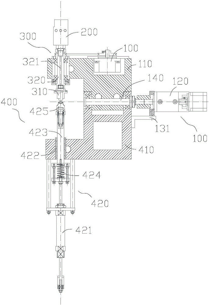
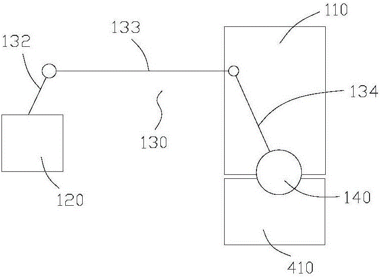
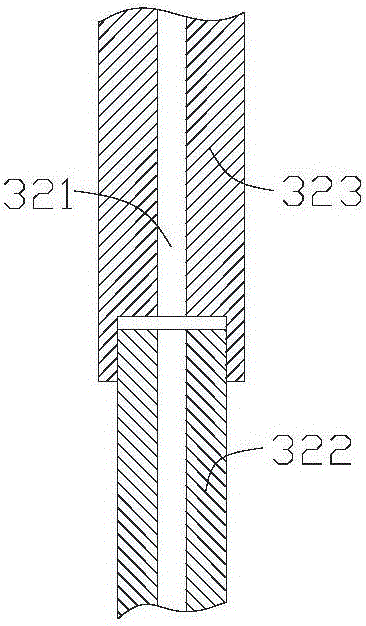

Image

  • Lens polishing machine and lens processing equipment
  • Lens polishing machine and lens processing equipment
  • Lens polishing machine and lens processing equipment

Examples


Embodiment Construction

[0029] The traditional polishing method for concave workpieces in traditional optical lenses is to use top-swing or bottom-swing polishing machines for processing. The polishing die rotates at a high speed with the main shaft at the bottom, and the upper pressure head presses the workpiece and rotates with the main shaft; the upper pressure head swings or the polishing die and the main shaft swing together; the concave surface of the workpiece is downward, matching the polishing die to achieve polishing. During the processing, the grinding fluid cannot enter the concave grinding part, which may easily cause insufficient polishing, poor workpiece surface shape, traces, and low efficiency, thereby increasing the probability of rework, resulting in an increase in the scrap rate of the workpiece and an increase in the production cost of the enterprise.

[0030] In view of this, the designer of the present invention has designed a kind of lens polishing machine and lens processing e...


PUM


Abstract

The invention provides a lens polishing machine and lens processing equipment, and belongs to the technical field of lens processing. The lens polishing machine comprises an upward swing mechanism, a polishing solution inner spraying mechanism, a polishing mechanism and an installing mechanism used for installing work-pieces, wherein the upward swing mechanism and the installing mechanism are vertically arranged in a spaced mode, the upward swing mechanism is located above the installing mechanism, the polishing mechanism is installed on the upward swing mechanism, the upward swing mechanism drives the polishing mechanism to swing relative to the installing mechanism, and an inner channel for a polishing solution to flow is formed between the polishing solution inner spraying mechanism and the polishing mechanism. According to the lens polishing machine, in the process of polishing a lens, sufficient polishing solutions exist between the grinding surface of a polishing mold and the contact positions of the work-pieces, the polishing solutions can make full contact with the work-pieces in the grinding process, fast and efficient polishing of the concave optical lens is effectively realized, and processing is efficient and stable.

Description

technical field [0001] The invention relates to the technical field of lens processing, in particular to a lens polishing machine and lens processing equipment. Background technique [0002] The traditional polishing method for concave workpieces in optical lenses is to use top-swing or bottom-swing polishing machines for processing. The polishing die rotates at a high speed with the main shaft at the bottom, and the upper pressure head presses the workpiece and rotates with the main shaft; the upper pressure head swings or the polishing die and the main shaft swing together; the workpiece matches the polishing die to achieve polishing. [0003] The inventor found in research that the processing of concave workpieces in traditional lenses has at least the following disadvantages: [0004] During the processing, the grinding fluid cannot enter the concave grinding part, which may easily cause insufficient polishing, poor workpiece surface shape, traces, and low efficiency, t...

Claims


Application Information

Patent Timeline
Patent Type & Authority Applications(China)
IPC IPC(8): B24B13/01B24B29/02B24B41/02B24B41/06
CPCB24B13/01B24B29/02B24B41/02B24B41/06
Inventor 李宏徐运波王国玉李晓亮
Owner 南阳中一光学装备有限公司
Learn More