Split wall hanging internal unit condensed water draining structure
A drainage structure and condensed water technology, which is applied in the prevention of condensed water, space heating and ventilation details, heating methods, etc., can solve the problems of easy blockage of drain outlets, etc., and achieve elongated cleaning cycle, extended cleaning cycle, and smooth water flow Effect
- Summary
- Abstract
- Description
- Claims
- Application Information
AI Technical Summary
Problems solved by technology
Method used
Image

Examples
Embodiment 1
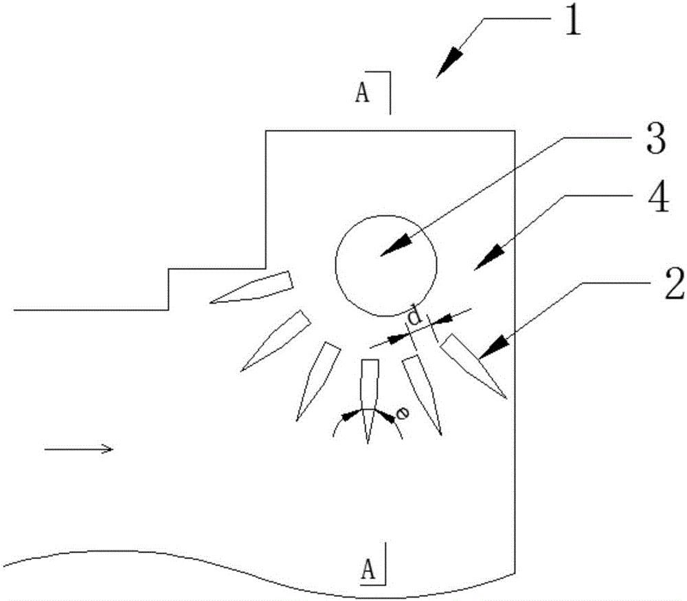
[0047] The condensed water drainage structure 1 of the split wall-mounted internal unit described in this embodiment, such as figure 1 , 2As shown, the drain port 3 is arranged on the water receiving tray 4, and a blocking member 2 suitable for passing the water flow and blocking the dirt is provided at the drain port 3 facing the direction of the water flow, that is, at the drain port of the water receiving tray 4 There are 3 installations that can not only allow the condensed water to pass through, but also block the dirt, so the dirt is not easy to block the drain pipe, so the cleaning cycle can be greatly extended. In this embodiment, the blocking member 2 is a plurality of cylinders distributed at intervals along the periphery of the drainage outlet 3 and having two surfaces connected at an intersection line at an included angle, and the angle of the included angle is e is 25°, and the intersection line faces away from the drain port 3 and is set parallel to the axis of ...
Embodiment 2
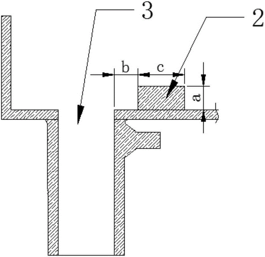
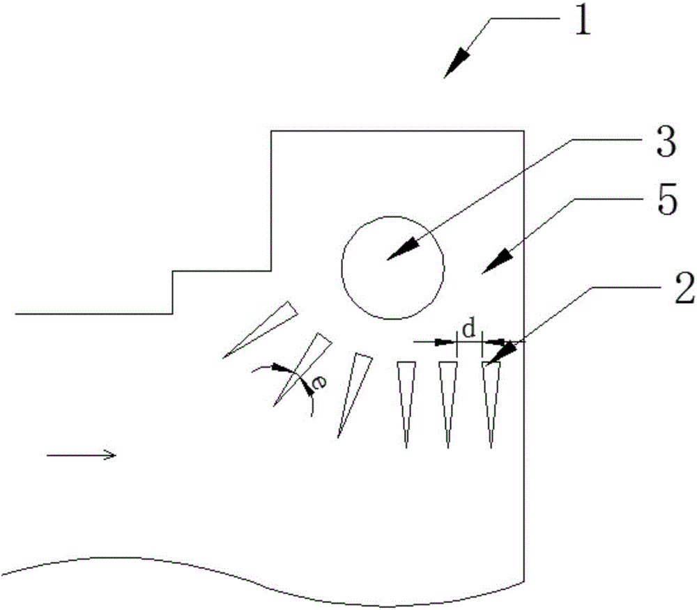
[0049] The condensed water drainage structure 1 of the split wall-mounted internal unit described in this embodiment, such as image 3 As shown, it is installed at the bottom 5 of the bottom case of the split wall-mounted inner machine, and the bottom 5 of the bottom case coincides with the water receiving tray 4, that is, the bottom case is used as the water receiving tray 4, and the bottom case is provided with a device for discharging The drain port 3 for condensed water is provided with a blocking member 2 suitable for the passage of water and blocking dirt on the drain port 3 facing the water flow direction. In this embodiment, the blocking member 2 is along the drain port 3 A number of cylinders distributed at intervals around the periphery have two surfaces and the two surfaces are connected at an intersection at an included angle. The cylinders are triangular columns, and the angle e of the included angle is 30°. The apex height c of the triangular prism is 4mm, the he...
Embodiment 3
[0051] The condensed water drainage structure 1 of the split wall-mounted internal unit described in this embodiment, such as image 3 As shown, it is installed at the bottom 5 of the bottom case of the split wall-mounted inner machine, and the bottom 5 of the bottom case coincides with the water receiving tray 4, that is, the bottom case is used as the water receiving tray 4, and the bottom case is provided with a device for discharging The drain port 3 for condensed water is provided with a blocking member 2 suitable for the passage of water and blocking dirt on the drain port 3 facing the water flow direction. In this embodiment, the blocking member 2 is along the drain port 3 Several cylinders distributed at intervals around the periphery have two surfaces and the two surfaces are connected at an intersection line at an angle, the cylinders are triangular columns, and the cross-section of the cylinders is an isosceles triangle. The angle e of the corner is 35°. The apex h...
PUM
 Abstract
Description
Claims
Application Information
 - Generate Ideas
- Intellectual Property
- Life Sciences
- Materials
- Tech Scout
- Unparalleled Data Quality
- Higher Quality Content
- 60% Fewer Hallucinations
Browse by: Latest US Patents, China's latest patents, Technical Efficacy Thesaurus, Application Domain, Technology Topic, Popular Technical Reports.
© 2025 PatSnap. All rights reserved.Legal|Privacy policy|Modern Slavery Act Transparency Statement|Sitemap|About US| Contact US: help@patsnap.com