Manufacturing technology of carbon fiber loading rod and carbon fiber loading rod

A manufacturing process and technology of carbon fiber rods, which is applied in the field of automobile engine testing experiments, can solve the problems of low overall strength of carbon fiber rods and loose bonding of carbon fiber rods, so as to avoid economic losses and personal injuries, avoid loose bonding, and improve strength Effect

Inactive Publication Date: 2017-05-24
SHANGHAI JINGZHI IND CO LTD
View PDF4 Cites 2 Cited by
  • Summary
  • Abstract
  • Description
  • Claims
  • Application Information

AI Technical Summary

Problems solved by technology

[0006] The purpose of the present invention is to propose a manufacturing process for a carbon fiber loading rod used in automobile engine testing to solve the problem of low overall strength of the carbon fiber rod caused by the loose combination of layers on the carbon fiber rod

Method used


Image

  • Manufacturing technology of carbon fiber loading rod and carbon fiber loading rod
  • Manufacturing technology of carbon fiber loading rod and carbon fiber loading rod
  • Manufacturing technology of carbon fiber loading rod and carbon fiber loading rod

Examples


Embodiment 1

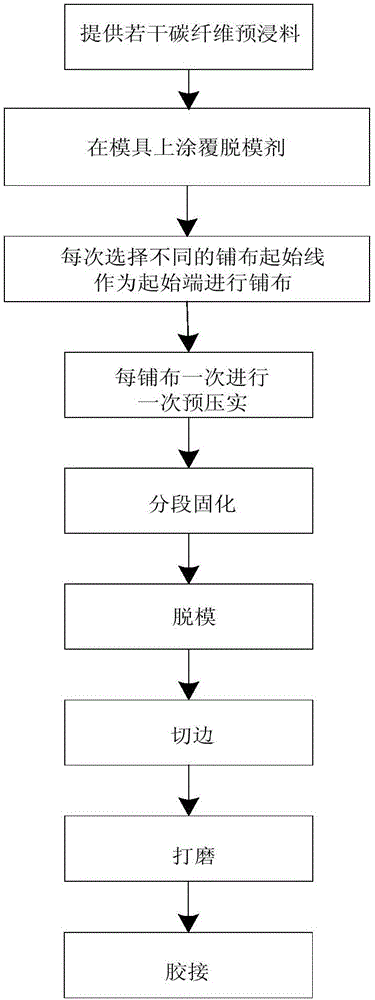
[0038] Such as Figure 1-Figure 3 As shown, Embodiment 1 provides a carbon fiber loading rod manufacturing process, including:

[0039] Step A: Provide a carbon fiber prepreg, the carbon fiber prepreg is T300 carbon fiber prepreg, and the dimension of the prepreg along the length direction forming the carbon fiber loading rod is 585 mm. The tensile strength of T300 is 3450MPa, the tensile modulus is 230GPa, the density is 1.8g / cm3, and the elongation at break is 1.5%. Compared with other metal materials, it has higher strength. In the case of the same volume, It has a smaller mass and is more suitable to be made into parts to meet the lightweight needs of the industry.

[0040] Step B: coating the mold 1 with a release agent, the release agent is a general release agent, which can be zinc stearate, calcium stearate or a combination thereof.

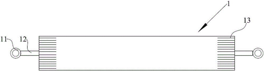
[0041] Step C: spread M layers of prepreg on the mold 1, the number of M is greater than or equal to two, the mold 1 is a pipe body, a...

Embodiment 2

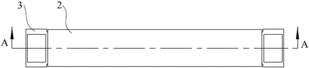
[0053] Such as Figure 2-Figure 4 As shown, Embodiment 2 provides a carbon fiber loading rod, which is manufactured using the carbon fiber loading rod manufacturing process as proposed in Embodiment 1.

[0054] In addition, the carbon fiber loading rod can also be composed of a metal end 3, a metal inner layer and a carbon fiber rod 2. The carbon fiber rod 2 is wrapped on the outer surface of the metal inner layer and fixed by resin connection. The end of the metal end 3 adopts a socket form Connected and fixed to the metal inner layer. The shape of the metal end 3 can be circular or polygonal. According to different occasions and different strengths required by the use of carbon fiber loading rods, the cross-sectional shape of the metal end 3, the metal inner layer and the carbon fiber rod 2 is changed, thereby improving the metal end 3. The connection strength between the metal inner layer and the carbon fiber rod 2.


PUM

PropertyMeasurementUnit
lengthaaaaaaaaaa
thicknessaaaaaaaaaa
tensile strengthaaaaaaaaaa

Abstract

The invention relates to the field of test experiments of automobile engines, in particular to a manufacturing technology of a carbon fiber loading rod for automobile engine testing and the carbon fiber loading rod. According to the manufacturing technology of the carbon fiber loading rod, multiple layers of prepreg are laid and distributed on a die, during each time of laying and distributing, different laying and distributing starting lines are selected to serve as starting ends, in the laying and distributing process, pre-compaction is carried out multiple times, and curing, die releasing, side cutting, grinding and assembling steps are carried out. Meanwhile, the invention discloses the carbon fiber loading rod. During each time of laying and distributing, the different laying and distributing starting lines are selected to serve as the starting ends, in the laying and distributing process, pre-compaction is carried out multiple times, gaps between layers of the prepreg of a carbon fiber can be effectively reduced, the whole strength of the carbon fiber loading rod can be effectively improved, bending or cracking phenomena appearing in the use process of the rod can be avoided, normal use performance of the carbon fiber loading rod is ensured, and unnecessary economic losses and personal injuries are avoided.

Description

technical field [0001] The invention relates to the field of automobile engine testing experiments, in particular to a manufacturing process of a carbon fiber loading rod used for automobile engine testing and the carbon fiber loading rod. Background technique [0002] With the continuous aggravation of the global greenhouse effect, global warming has become a major concern of the world today. On December 12, 2015, representatives of 196 countries signed the "United Nations Framework Convention on Climate Change" in Paris. This document stipulates the amount of greenhouse gas emissions after 2020 and proposes measures to prevent climate change. As a developing country, China has also set goals for energy conservation, emission reduction, technological upgrading and adaptation to climate change. With the rapid development of China's auto industry, energy saving, safety, and environmental protection are the three major themes of the development of the auto industry. The light...

Claims


Application Information

Patent Timeline
Patent Type & Authority Applications(China)
IPC IPC(8): B29C70/34B29C70/54G01M15/02
CPCB29C70/34B29C70/54G01M15/02
Inventor 荣朝运陈海棠孟西陵李湘坤宋月红
Owner SHANGHAI JINGZHI IND CO LTD
Why Eureka
Try Eureka