A collector and exhaust pipe welding fixture

A technology for welding fixtures and exhaust pipes, applied in welding equipment, auxiliary welding equipment, welding/cutting auxiliary equipment, etc., can solve the problem of poor mechanical strength at the connection between the collector and the exhaust pipe, and poor uniformity of solder flow on the welding sealing surface , Collector and exhaust pipe vertical difference, etc., to achieve the effect of ensuring consistent welding quality, convenient processing, and simple structure

Active Publication Date: 2018-09-28
CHENGDU GUOGUANG ELECTRIC
View PDF6 Cites 0 Cited by
  • Summary
  • Abstract
  • Description
  • Claims
  • Application Information

AI Technical Summary

Problems solved by technology

In the process of miniaturization of the traveling wave tube, the axial extraction of the exhaust pipe can no longer meet the miniaturization requirements of the traveling wave tube, and the requirement for the exhaust pipe to be axially drawn out from the collector is proposed. However, the electron gun housing and exhaust During the welding process of the air pipe, the verticality between the collector and the exhaust pipe is poor, the mechanical strength of the connection between the collector and the exhaust pipe is poor, and the uniformity of solder flow on the welding sealing surface is poor, which leads to poor air tightness of the sealing surface. And the poor consistency of batch welding

Method used


Image

  • A collector and exhaust pipe welding fixture
  • A collector and exhaust pipe welding fixture
  • A collector and exhaust pipe welding fixture

Examples


Embodiment 1

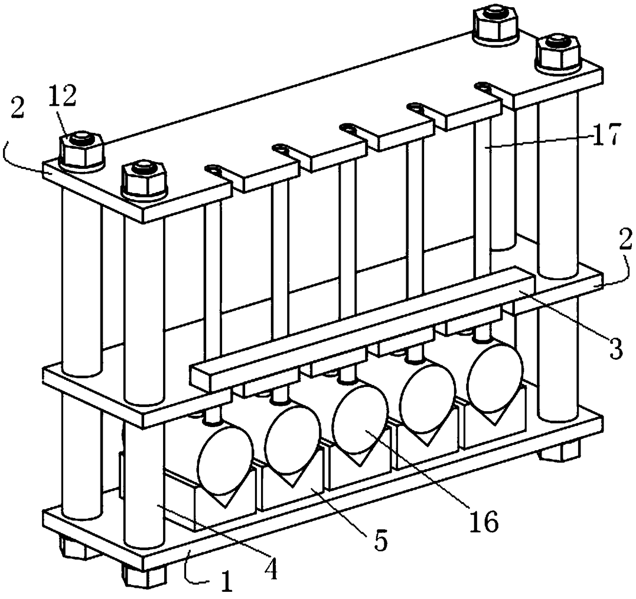
[0025] The collector and exhaust pipe welding fixture in Embodiment 1, the welding fixture includes a base, two positioning seats, a connecting rod and a support for placing the collector to be welded; the base and the positioning seats are connected sequentially from bottom to top The rods are connected and fixed; the base, the positioning seat, the connecting rod and the support are all made of metal materials whose melting point is higher than the melting point of the solder; the described clamp for the collector and exhaust pipe welding machine, the base, The positioning piece and the positioning seat are strip-shaped.

[0026] - The base is provided with a base positioning cylinder for installing the connecting rod and a plane for placing the support, and the base positioning cylinder is coaxial with the connecting rod;

[0027] -The positioning seat is provided with at least one loading and unloading positioning groove for loading and unloading the exhaust pipe to be exh...

Embodiment 2

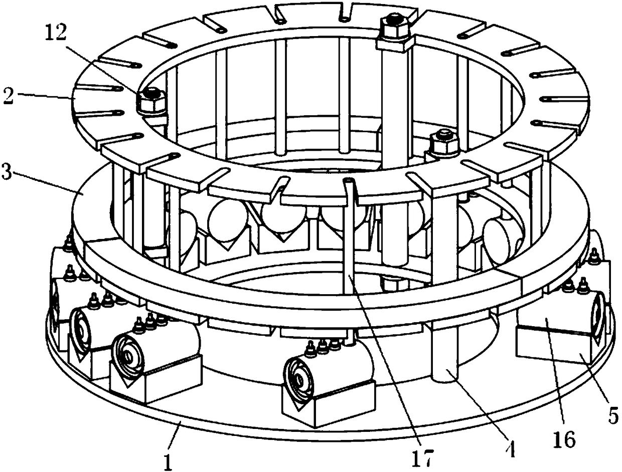
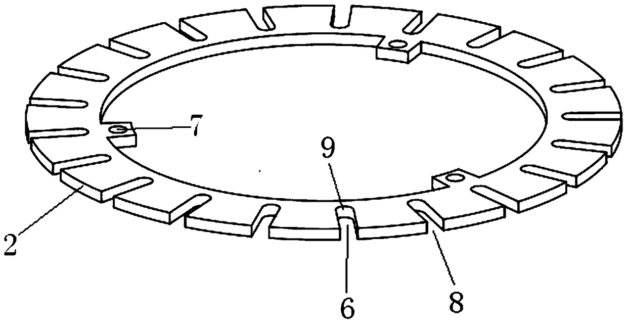
[0031] The collector and exhaust pipe welding fixture in the second embodiment, the welding fixture includes a base, two positioning seats, a connecting rod and a support for placing the collector to be welded; the base and the positioning seats are connected sequentially from bottom to top The rods are connected and fixed; the base, the positioning seat, the connecting rod and the support are all made of metal materials whose melting point is higher than the melting point of the solder; the described clamp for the collector and exhaust pipe welding machine, the base, The positioning piece and the positioning seat are disc-shaped.

[0032] - The base is provided with a base positioning cylinder for installing the connecting rod and a plane for placing the support, and the base positioning cylinder is coaxial with the connecting rod;

[0033] -The positioning seat is provided with at least one loading and unloading positioning groove for loading and unloading the exhaust pipe t...


PUM


Abstract

The invention discloses a collector and exhaust pipe welding fixture. The collector and exhaust pipe welding fixture comprises a base, two positioning seats, connecting rods and supporting pieces where to-be-welded collectors can be placed; the base and the positioning seats are sequentially connected and fixed through the connecting rods from bottom to top; the base, the positioning seats, the connecting rods and the supporting pieces are all made of metal materials of which the melting point is higher than that of soldering flux; the base is provided with base positioning column faces for installing the connecting rods, and a plane where the supporting pieces can be placed; the base positioning column faces and the connecting rods are coaxial; each positioning seat is provided with at least one assembling-disassembling positioning groove for assembling and disassembling to-be-welded exhaust pipes, and positioning seat positioning column faces; one ends of the assembling-disassembling positioning grooves are provided with open ends, and the other ends of the assembling-disassembling positioning grooves are provided with positioning holes; and the assembling-disassembling positioning grooves of the upper positioning seat and the assembling-disassembling positioning grooves of the lower positioning seat are formed in a one-to-one correspondence mode, the axes of the positioning holes corresponding to the assembling-disassembling positioning grooves are coaxial and perpendicular to the plane where the base is located. According to the collector and exhaust pipe welding fixture, the perpendicularity of the symmetry axes of the exhaust pipes and the column faces of collectors can be effectively ensured, and the coaxiality between the exhaust pipe welded column faces and the collector welded column faces is ensured.

Description

technical field [0001] The invention relates to a welding jig, in particular to a welding jig used in the manufacturing process of an electric vacuum device. Background technique [0002] Traveling wave tube is an important electronic device in the fields of microwave relay communication, radar, electronic countermeasures and satellite communication. The exhaust pipe of the traveling wave tube is generally led out from the axial direction to discharge the gas in the cavity of the traveling wave tube. In the process of miniaturization of the traveling wave tube, the axial extraction of the exhaust pipe can no longer meet the miniaturization requirements of the traveling wave tube, and the requirement for the exhaust pipe to be axially drawn out from the collector is proposed. However, the electron gun housing and exhaust During the welding process of the air pipe, the verticality between the collector and the exhaust pipe is poor, the mechanical strength of the connection be...

Claims


Application Information

Patent Timeline
Patent Type & Authority Patents(China)
IPC IPC(8): B23K37/04
CPCB23K37/04B23K37/0443B23K2101/36
Inventor 高翔陈涛王曙光邱葆荣陈燕甘琦朱文晗卢秀琴
Owner CHENGDU GUOGUANG ELECTRIC
Why Eureka
Try Eureka